Electromagnetic wave resistivity tool having a tilted antenna for geosteering within a desired payzone

a technology of electromagnetic wave resistivity and geosteering, which is applied in the direction of instruments, borehole/well accessories, surveys, etc., can solve the problems of reducing the mechanical strength of the tool, and affecting the accuracy of the tool

Inactive Publication Date: 2002-11-05
HALLIBURTON ENERGY SERVICES INC
View PDF30 Cites 293 Cited by
  • Summary
  • Abstract
  • Description
  • Claims
  • Application Information

AI Technical Summary

Problems solved by technology

However, each of the existing techniques suffers from one or more disadvantages.
However, such orthogonal coil (antenna) configurations are not generally considered practical for a measuring while drilling (MWD) or logging while drilling (LWD) tool because, if the coil is located in the interior of the tool, the presence of the coil necessitates a non-conventional mud flow path and decreases the mechanical strength of the tool.
If, on the other hand, the additional coil is located on the exterior of the tool, the coil is susceptible to damage by formation cuttings in the return mud flow.
However, the '448 patent, which discloses a conventional antenna configuration in which the transmitter and receiver coils are aligned co-axially with the tool, does not provide a way to determine the relative dip angle.
However, Hagiwara's method does not provide the relative dip angle.
Moreover, Hagiwara showed that, for conventional induction logging tools (in which the transmitter and receiver antennas are oriented co-axially with the tool), it is impossible to obtain all three parameters (horizontal resistivity, vertical resistivity, and relative dip angle) simultaneously.
The reason such a simultaneous solution is not possible using conventional induction logging tools is that, in the response of such tools, the vertical resistivity and the relative dip angle are coupled (i.e., they are not independent).
Therefore, even if the dielectric constants are known, the vertical resistivity and the relative dip angle are still coupled and do not allow for a simultaneous solution.
Consequently, as a conventional resistivity tool approaches a bed boundary between a first bed having one resistivity and a second bed having a different resistivity, Luling's method indicates only the presence of the boundary; Luling's method does not provide an early indication of whether the resistivity of the second bed is higher or lower than that of the first bed.
As a result, Luling's method may lead to unnecessary penetrations into undesirable beds.
The method of Wu and Wisler involves significant drawbacks in terms of the time, expense, and uncertainty associated with such a reference resistivity log.
However, such electrode resistivity tools operate by forcing electric current into an earth formation by direct conduction, which requires conductive mud.
Consequently, such electrode resistivity tools will not function properly in oil-based mud or in the presence of resistive invasion.
Although the '616 apparatus provides directional sensitivity which may be helpful in steering a drilling tool, the '616 patent does not teach how to utilize a transmitter and a receiver oriented at arbitrary inclination angles with respect to each other in order to take advantage of the special characteristics of the horns in the resulting response.

Method used


Image

  • Electromagnetic wave resistivity tool having a tilted antenna for geosteering within a desired payzone
  • Electromagnetic wave resistivity tool having a tilted antenna for geosteering within a desired payzone
  • Electromagnetic wave resistivity tool having a tilted antenna for geosteering within a desired payzone

Examples


Embodiment Construction

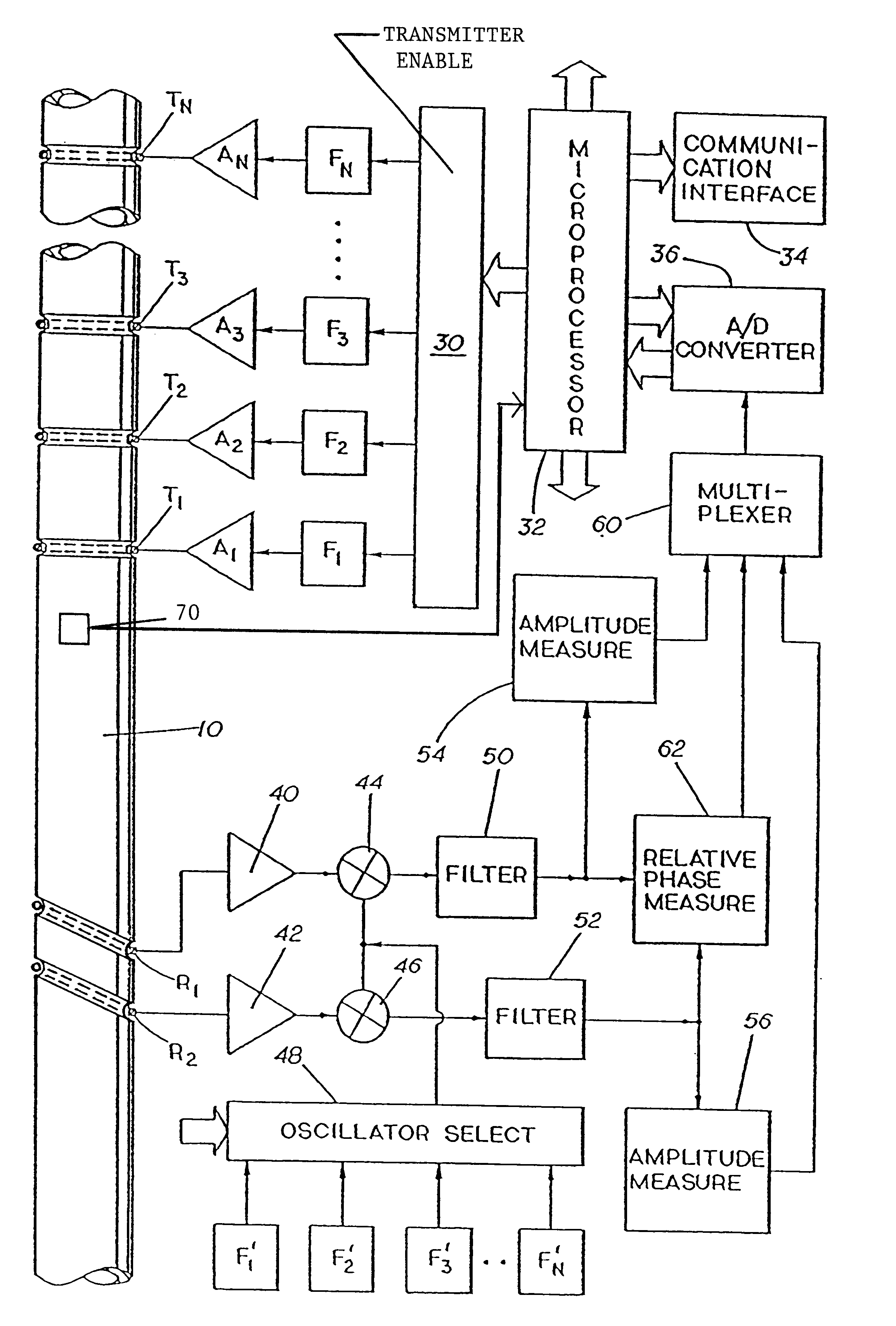
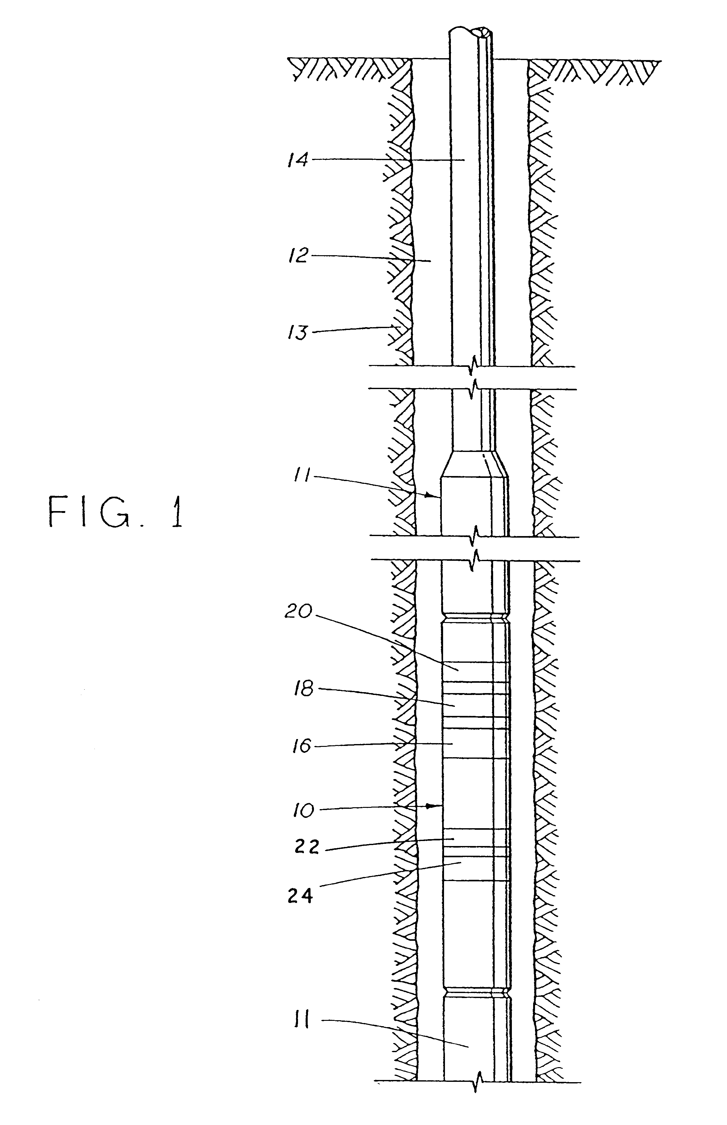
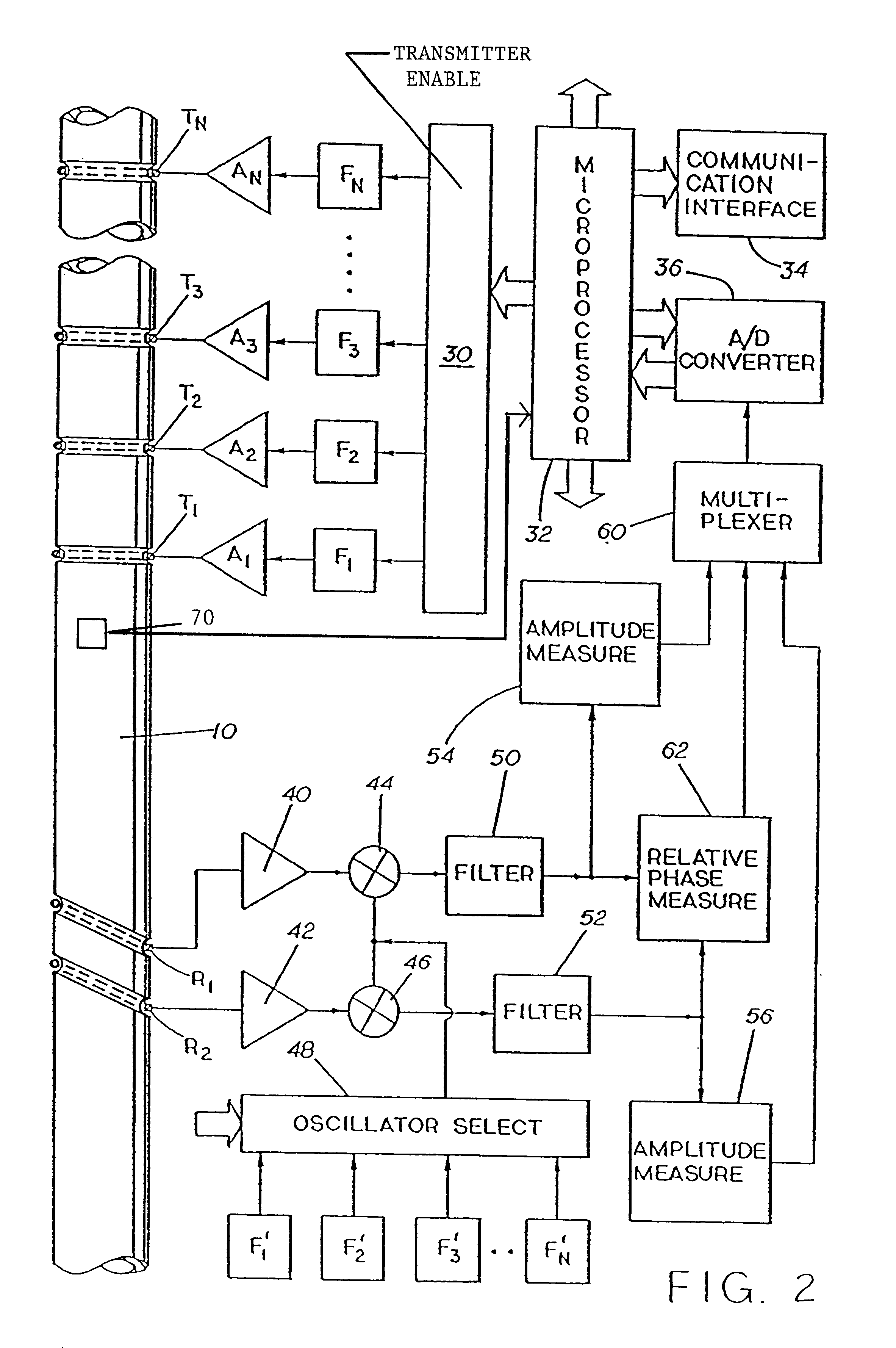
FIG. 1 illustrates a logging tool 10 in accordance with the present invention suspended in a borehole 12 within an earth formation 13 on a string of drill pipe 14. Drill string 14 includes one or more drill collars 11. Electromagnetic transmitters (antennas) 16, 18, and 20 (sometimes referred to herein as transmitters T.sub.1, T.sub.2, and T.sub.3, respectively) are spaced along the length of logging tool 10 from electromagnetic receivers (antennas) 22 and 24 (sometimes referred to herein as R.sub.1 and R.sub.2, respectively). Preferably, transmitters 16, 18, 20 and receivers 22, 24 are mounted in recesses in tool 10 (as indicated in FIG. 2) and are covered with a non-conductive material (not shown), as is well known in the art. If a transmitter is designed to operate at more than one frequency, for example, f.sub.1 =2 MHz and f.sub.2 =1 MHz, each receiver may comprise a pair of coils, with one coil tuned to f.sub.1 and one coil tuned to f.sub.2. Additionally, if desired, each pair ...


PUM


Abstract

This invention is directed to a downhole method and apparatus for simultaneously determining the horizontal resistivity, vertical resistivity, and relative dip angle for anisotropic earth formations. The present invention accomplishes this objective by using an antenna configuration in which a transmitter antenna and a receiver antenna are oriented in non-parallel planes such that the vertical resistivity and the relative dip angle are decoupled. Preferably, either the transmitter or the receiver is mounted in a conventional orientation in a first plane that is normal to the tool axis, and the other antenna is mounted in a second plane that is not parallel to the first plane. This invention also relates to a method and apparatus for steering a downhole tool during a drilling operation in order to maintain the borehole within a desired earth formation. The steering capability is enabled by computing the difference or the ratio of the phase-based or amplitude-based responses of the receiver antennas which are mounted in planes that are not parallel to the planes of the transmitter antennas. Although this invention is primarily intended for MWD or LWD applications, this invention is also applicable to wireline and possibly other applications.

Description

1. Field of the InventionThis invention relates generally to a method and apparatus for determining the horizontal and vertical resistivities and the relative dip angle of a borehole in an electrically anisotropic earth formation. More specifically, this invention relates to an electromagnetic wave induction technique for measuring resistivity using a tool having an antenna that is disposed within a plane which is inclined with respect to a plane that is normal to the axis of the tool. This invention also relates to a method and apparatus for steering a downhole tool during a drilling operation in order to maintain the borehole within a desired earth formation.2. Description of the Related ArtIn the field of petroleum well drilling and logging, electromagnetic wave resistivity sensors are frequently used to provide an indication of the electrical resistivity of rock formations surrounding an earth borehole. Such information regarding resistivity is useful in ascertaining the presenc...

Claims


Application Information

Patent Timeline
Patent Type & Authority Patents(United States)
IPC IPC(8): G01V3/28G01V3/18
CPCG01V3/28G01V3/30E21B47/0228
Inventor BITTAR, MICHAEL S.
Owner HALLIBURTON ENERGY SERVICES INC
Why Eureka
Try Eureka