
Electromagnetic driving valve of internal combustion engine

a technology of electric motor and internal combustion engine, which is applied in the direction of valve operating means/release devices, non-mechanical valves, machines/engines, etc., can solve the problems of shaft contact, impact sound and vibration, and valve closing

Inactive Publication Date: 2002-11-12
HONDA MOTOR CO LTD
View PDF4 Cites 9 Cited by
  • Summary
  • Abstract
  • Description
  • Claims
  • Application Information

AI Technical Summary

Benefits of technology

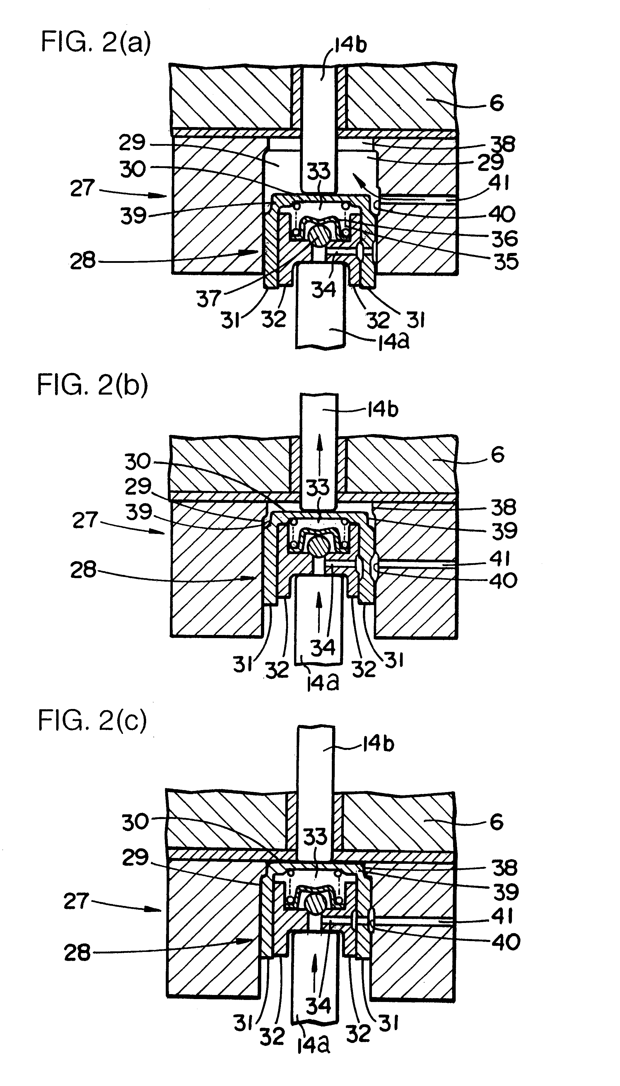
a fluid receiving portion slidably inserting the contact connecting means thereto and gradually discharging a fluid charged in an inner portion thereof together with an upward movement of the contact connecting means at a time of a valve closing operation of the valve portion, thereby reducing a valve closing speed of the valve portion via the first transmission shaft.
Accordingly, since a diameter of the fluid discharging passage formed between the inner peripheral wall of the fluid receiving portion and the outer peripheral wall of the overcoat member in the contact connecting means is made small when the second small diameter portion moves forward to the first small diameter portion in accordance with the upward movement of the overcoat member within the fluid receiving portion, it is possible to reduce the discharging amount of the fluid immediately before the valve portion is brought into contact with the intake and exhaust port. Accordingly, it is possible to make the structure significantly simple and it is possible to smoothly execute a sudden speed reduction of the valve portion immediately before closing the valve.

Problems solved by technology

Accordingly, since a displacement speed of the movable plate is increased in accordance that the movable plate moves close to the electromagnet, and the valve portion quickly sits on the intake and exhaust port in accordance therewith, there is a disadvantage that an impact sound and a vibration are generated at a time of closing the valve.
Accordingly, when the movable plate moves apart from the upper electromagnet toward the lower electromagnet at a time of a valve opening operation, there is a disadvantage that the second transmission shaft comes into contact with the first transmission shaft, whereby the impact sound and the vibration are also generated from a contact portion between both of the transmission shafts.

Method used


Image

  • Electromagnetic driving valve of internal combustion engine
  • Electromagnetic driving valve of internal combustion engine
  • Electromagnetic driving valve of internal combustion engine

Examples


Embodiment Construction

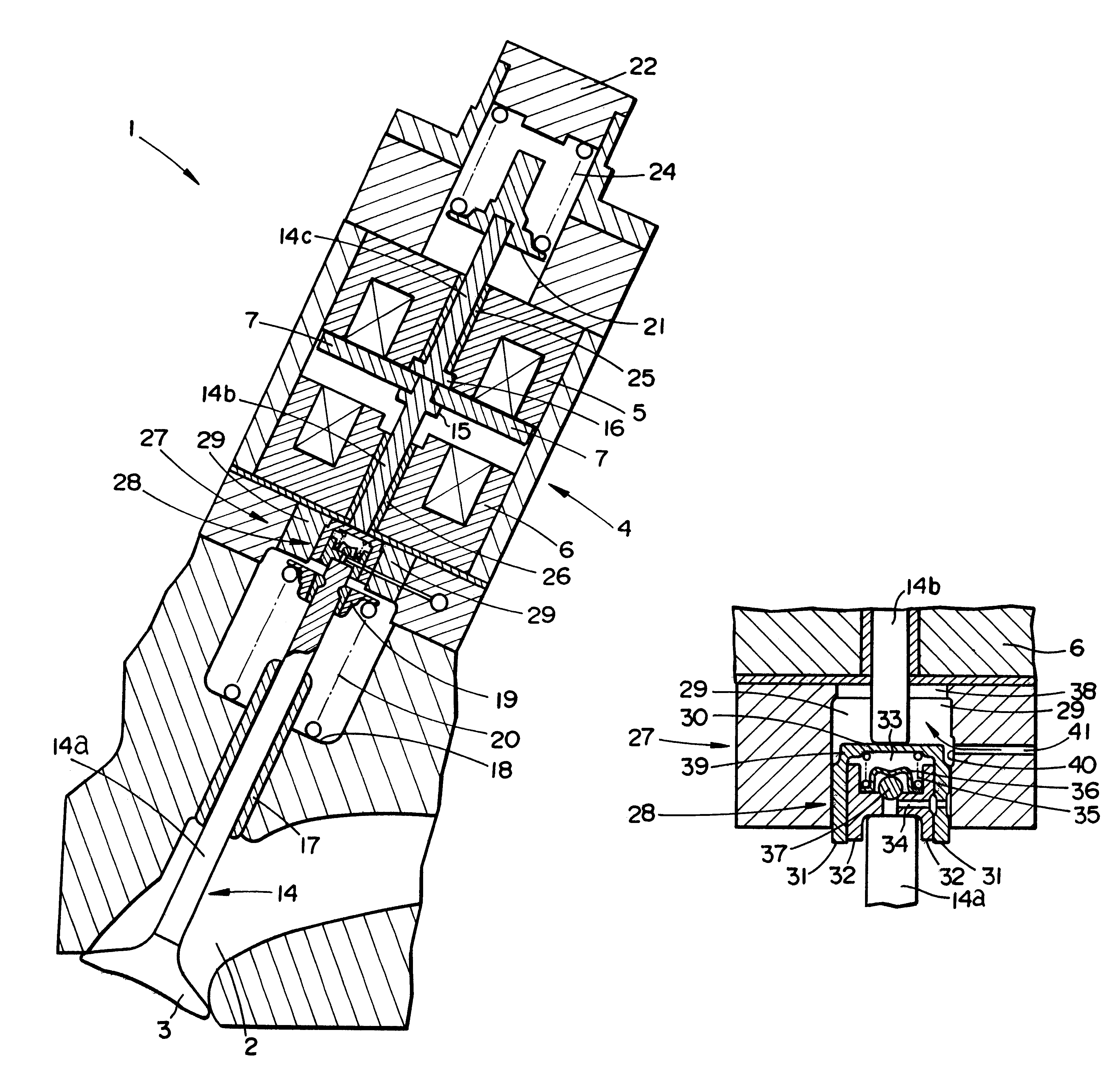
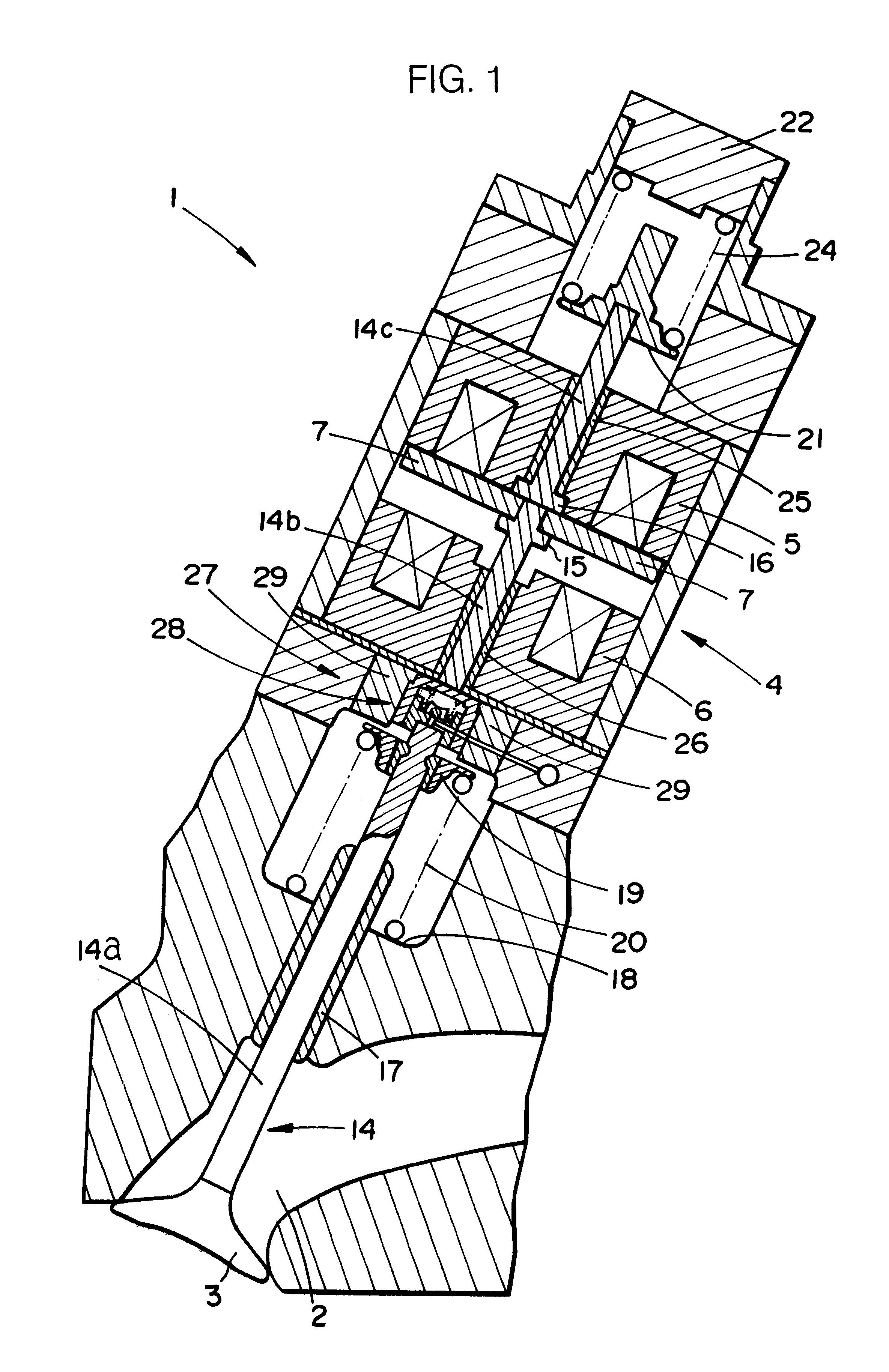
A description will be given of an embodiment in accordance with the present invention with reference to the accompanying drawings. FIG. 1 is a schematic vertical cross sectional view showing an electromagnetic driving valve in accordance with the present embodiment, and FIGS. 2A, 2B and 2C are schematic views showing an operation of a shock absorbing means.

An electromagnetic driving valve 1 in accordance with the present embodiment is provided, as shown in FIG. 1, in an intake (or exhaust) passage 2 of an internal combustion engine, and is constituted by a valve portion 3 opening and closing the intake passage 2, and a driving portion 4 driving the valve portion 3 in an opening and closing direction. The driving portion 4 is constituted by a first electromagnet 5 provided at an upper position in FIG. 1, a second electromagnet 6 provided at a position below the first electromagnet 5 in an opposing manner, and a movable plate 7 positioned between both of the electromagnets 5 and 6. Th...


PUM


Abstract

The invention provides an electromagnetic driving valve of an internal combustion engine provided with a significantly compact shock absorbing means which can reduce an impact sound and a vibration in a contact portion between a first transmission shaft and a second transmission shaft and reduce an impact sound and a vibration generated at a time when a valve portion sits on an intake and exhaust port at a time of closing a valve. A shock absorbing means (27) is provided between a first transmission shaft (14a) extended upward from a valve portion (3) and a second transmission shaft (14b) extended on the same axis thereof and supporting a movable plate (7) between a pair of electromagnets (5, 6). The shock absorbing means (27) is provided with a contact connecting means (28) connected to an upper end of the first transmission shaft (14a) and freely extending and compressing while maintaining a contact with a lower end of the second transmission shaft (14b), and an oil receiving portion (29) slidably inserting the contact connecting means (28) thereto and gradually discharging a fluid charged in an inner portion thereof together with an upward movement of the contact connecting means (28) at a time of a valve closing operation of the valve portion (3), thereby reducing a valve closing speed of the valve portion (3) via the first transmission shaft (14a).

Description

1. Field of the InventionThe present invention relates to an electromagnetic driving valve of an internal combustion engine for opening and closing an intake and exhaust port of an internal combustion engine.2. Description of the Prior ArtConventionally, there has been known an electromagnetic driving valve for driving a valve portion opening and closing an intake and exhaust port of an internal combustion engine, by an electromagnet. This kind of electromagnetic driving valve is provided with a movable plate connected to a transmission shaft extending to the above of the valve portion, and a pair of electromagnets vertically opposing to each other via the movable plate. The movable plate is sucked due to an electromagnetic force which both of the electromagnets alternately generate, thereby moving between both of the electromagnets. Further, when the movable plate is adsorbed to the upper electromagnet, the valve portion closes the intake and exhaust port, and when the movable plat...

Claims


Application Information

Patent Timeline
Patent Type & Authority Patents(United States)
IPC IPC(8): F01L9/04F01L1/245F01L1/20F01L1/16F01L9/20F01L1/24
CPCF01L1/245F01L9/04F01L9/20
Inventor UMEMOTO, ATSUSHIABE, KENJIONOHARA, YOSHINORIIKOMA, KOUICHI
Owner HONDA MOTOR CO LTD
Learn More