Apparatus and process for making prosthetic suction sleeve

a prosthetic and suction sleeve technology, applied in the field of process and apparatus for making prosthetic suction sleeve, can solve the problems of many different procedures, high cost and time-consuming, and complicated process, and achieve the effect of improving the quality of prosthetic suction sleeve, reducing the cost of treatment, and improving the quality of treatmen

Inactive Publication Date: 2002-11-26
KAUPTHING BANK
View PDF14 Cites 244 Cited by
  • Summary
  • Abstract
  • Description
  • Claims
  • Application Information

AI Technical Summary

Problems solved by technology

The process is more complicated when a distal prosthetic connector fitting must be incorporated in the distal end of the suction liner, particularly when an injection molding procedure is utilized.
Injection molding procedures are time consuming and require complex equipment to ensure accurate shapes and thicknesses of various size suction liners.
Injection molding thick, soft elastomeric layers on the inner surfaces of suction liners also present a challenge using injection molding techniques.
Prior art procedures for continuously coating tubular substrates with a cured elastomer coating or film involve many different procedures that tend to be expensive and time consuming.

Method used


Image

  • Apparatus and process for making prosthetic suction sleeve
  • Apparatus and process for making prosthetic suction sleeve
  • Apparatus and process for making prosthetic suction sleeve

Examples


Embodiment Construction

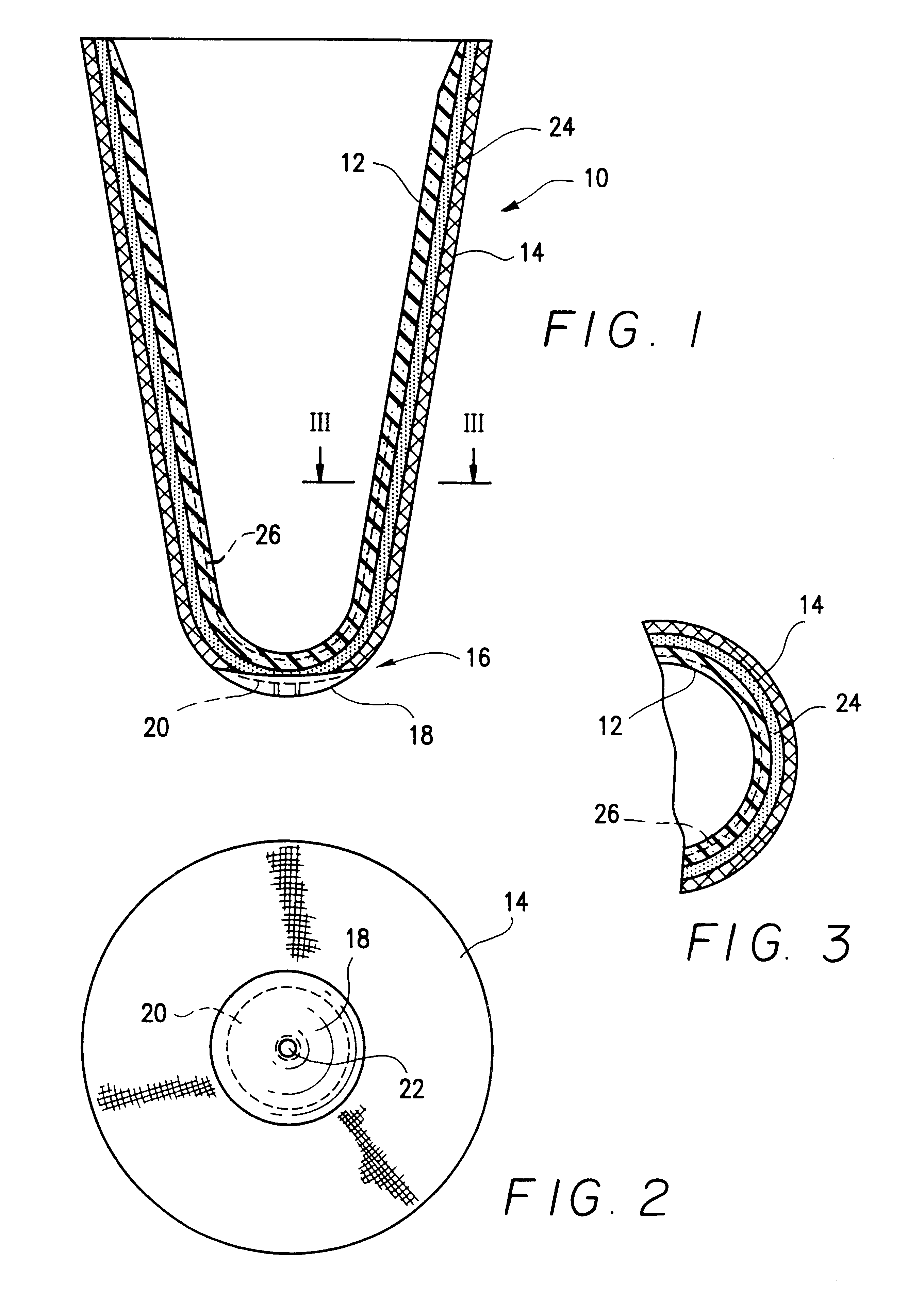
FIG. 1 schematically illustrates in a cross-section view a prosthetic suction liner 10 that may be formed using the process and apparatus described herein. The liner is formed in part of a composite elastic material 12 on its interior surface and an elasticized fabric layer 14 on its exterior surface at least up to its distal end area 16, where a distal end cap 18 having embedded therein a rigid prosthetic connector 20 formed, for example, of aluminum or other metal, or rigid plastic such as Nylon, is provided.

The liner 10 is formed as a close ended tapered tubular element, as is conventional for such suction liners. The distal end cap 18 firmly joins the prosthetic connector 20 to the suction liner 10 while providing a cushioning and stabilizing surface at the distal end of the liner. The prosthetic connector 20 includes preferably a threaded aperture 22 for providing access to a threaded prosthetic pin connector in a manner well known in the art.

FIG. 2 shows the suction liner in a...


PUM

PropertyMeasurementUnit
densityaaaaaaaaaa
densityaaaaaaaaaa
densityaaaaaaaaaa

Abstract

The method of making a tubular member having a continuous and uninterrupted cured elastomeric resin coating on an outer surface of the member includes forming a continuous uninterrupted tubular layer of uncured elastomeric resin and drawing the resin layer against the surface of the tubular member to be coated by applying suction between the resin layer and the surface of the tubular member so that the resin adheres to the surface of the tubular member. The elastomeric resin may then be continuously heated and cured to produce the final product. Apparatus for carrying out the process is disclosed and includes, in sequence, a coating zone including a sub-atmospheric chamber, a heating zone and a feed mechanism for advancing the tubular member relative to the coating and heating zones.

Description

1. Field of the Invention This invention relates to the process and apparatus for making prosthetic suction liners and coating tubular substrates.2. Background of the InventionProsthetic suction liners have been described in U.S. Pat. No. 4,923,474 granted to Klasson and Kristinsson on May 8, 1990; U.S. Pat. No. 5,728,168 granted Mar. 17, 1998 to Laghi et al.; and U.S. Pat. No. 5,830,237 granted to Kania Nov. 3, 1998.The original suction liner as described in U.S. Pat. No. 4,923,474 was formed of a silicone elastomer and was adapted to the rolled over residual limb of a prosthetic user in a manner fully described in the patent.The manufacturing process for making suction liners with a fabric exterior covering adhered to one or more cured elastomer inner layers typically involves multiple injection molding procedures and possibly laminating procedures that are designed to build-up the various layers constituting the suction liner. Obtaining an intimate bond between the silicone and f...

Claims


Application Information

Patent Timeline
Patent Type & Authority Patents(United States)
IPC IPC(8): A61F2/50A61F2/80A61F2/78A61L27/44A61L27/00B29C43/36B29C43/18B29C70/04B29C70/46B29C70/44B29D23/00A61F2/00B29C35/02B29C49/02A61F2/04A61L15/00B29D28/00
CPCA61F2/5046A61L27/44B29C43/183B29C43/361B29C70/44B29C70/467B29D23/001A61F2/7812B29C43/18A61F2/5044C08L83/04Y10T428/1362A61F2002/3007A61F2002/5007A61F2002/5053A61F2002/802B29B2911/14653B29C35/02B29C49/02B29K2083/005B29K2105/04B29K2105/0809B29K2105/0854B29K2105/0872B29K2105/246B29L2009/00B29L2023/007B29L2031/7532Y10T428/139B29D23/00A61F2002/5055A61F2002/7818A61F2002/7875Y10T428/1393Y10T442/40Y10T442/444B29C2949/082A61F2/50
Inventor JANUSSON, HILMARTHORSTEINSSON, FREYGAROURASGEIRSSON, SIGUROUR A.EINARSSON, PALMI
Owner KAUPTHING BANK
Why Eureka
Try Eureka