Malleolar implant for partial or total ankle prosthesis

a technology of malleolar implants, which is applied in the field of malleolar implants for partial or total ankle prosthesis, can solve the problems of limited access to the internal articular surface, difficulty in positioning the implant, and insufficient positioning of malleolar implants in the known prosthesis

Inactive Publication Date: 2002-12-03
SMITH & NEPHEW INC
View PDF11 Cites 81 Cited by
  • Summary
  • Abstract
  • Description
  • Claims
  • Application Information

AI Technical Summary

Benefits of technology

Thanks to the invention, the implant may be pre-positioned towards the inner face of the fibular malleolus and pulled through the through bore provided in the malleolus, with the result that the surgeon does not have to manipulate the implant with precision inside the joint, i.e. between the fibula and the tibia or between the fibula and the astragalus. The surgeon may exert an efficient effort on the traction member, which may be a flexible tie such as a suture thread, without being hindered by the surrounding bones. As a result, the positioning of the shank of the implant in the bore in the fibula may be precise, in particular due to the fact that the outer diameter of the shank may be substantially equal to the inner diameter of this bore, as the effort of traction which may be exerted from the outside of the fibula may be intense.
According to another advantageous aspect of the invention, the shank is provided with means for axial hold inside the bore. These means, which may be formed by outer radial flanges distributed over the length of the shank, make it possible efficiently to immobilize the shank inside the bore after it has been introduced therein by traction on the flexible member or tie.
According to an advantageous aspect of the invention, the spacer block is provided with a housing for receiving a shim of thickness adapted to the distance between the lower surface of the tibia and upper surface of the astragalus. This aspect of the invention makes it possible to maintain a distance corresponding to that which will be subsequently created by the prosthetic elements mounted in the lower part of the tibia and in the upper part of the astragalus, when the position of the malleolar implant is determined.
According to another advantageous aspect of the invention, the lug is articulated on the spacer block, with a limited possibility of pivoting. This makes it possible to adjust the position of the malleolus bore guide about the pivot axis of the lug with respect to the spacer block. In that case the spacer block and the lug are advantageously provided with orifices for passage of a common pivot pin.
It is also possible for the bore guide to be associated with a device for clamping the malleolus against a bearing surface formed on the lug or the spacer block. This allows a firm immobilization of the fibular malleolus during boring and thus ensures precision of the boring operation.

Problems solved by technology

During an operation on an ankle, access to the internal articular surfaces is limited by the ligamentary system which does not necessarily allow a sufficient dislocation of the joint.
In particular, access to the internal surface of the fibular malleolus may be insufficient, which induces difficulties in positioning the implant, particularly by impaction.
However, this necessarily limits the surface of the head of this implant, which must be less than or equal to the surface of the orifice provided in the bone, so that it is necessarily of relatively small dimensions with the result of substantially fragilizing the malleolus.
For the foregoing reasons, the positioning of the malleolar implants in the known prostheses is not entirely satisfactory.

Method used


Image

  • Malleolar implant for partial or total ankle prosthesis
  • Malleolar implant for partial or total ankle prosthesis
  • Malleolar implant for partial or total ankle prosthesis

Examples


Embodiment Construction

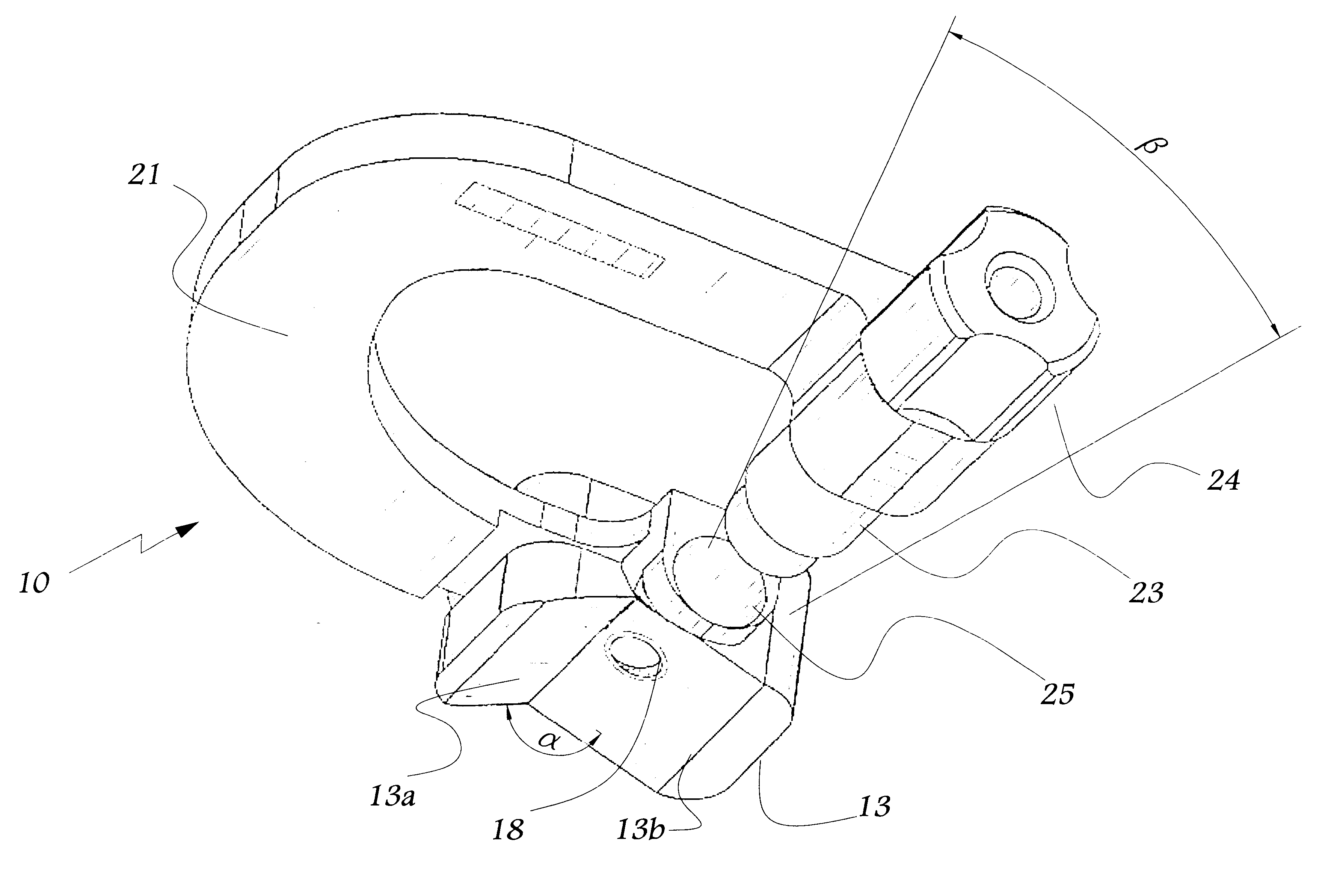
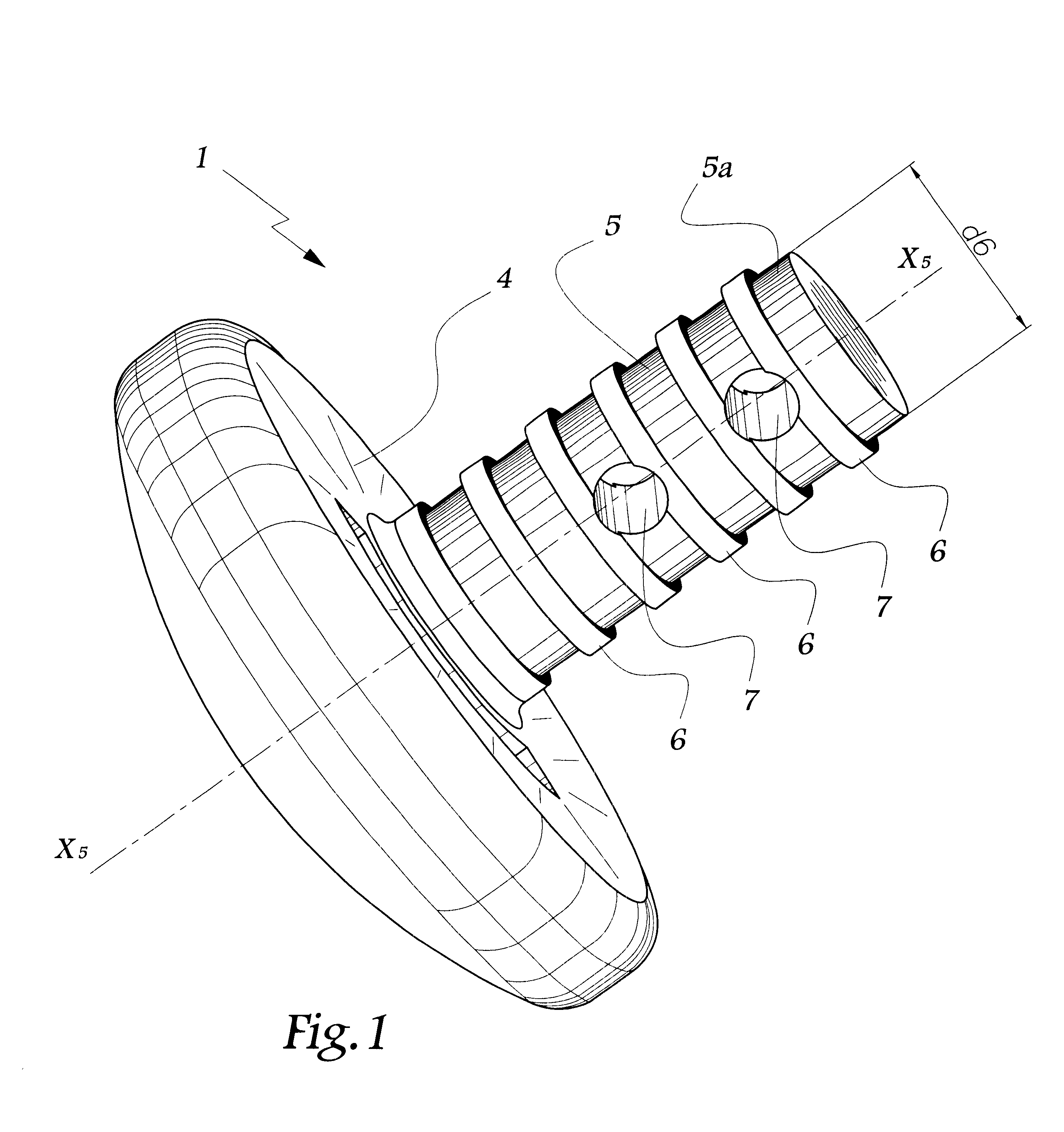
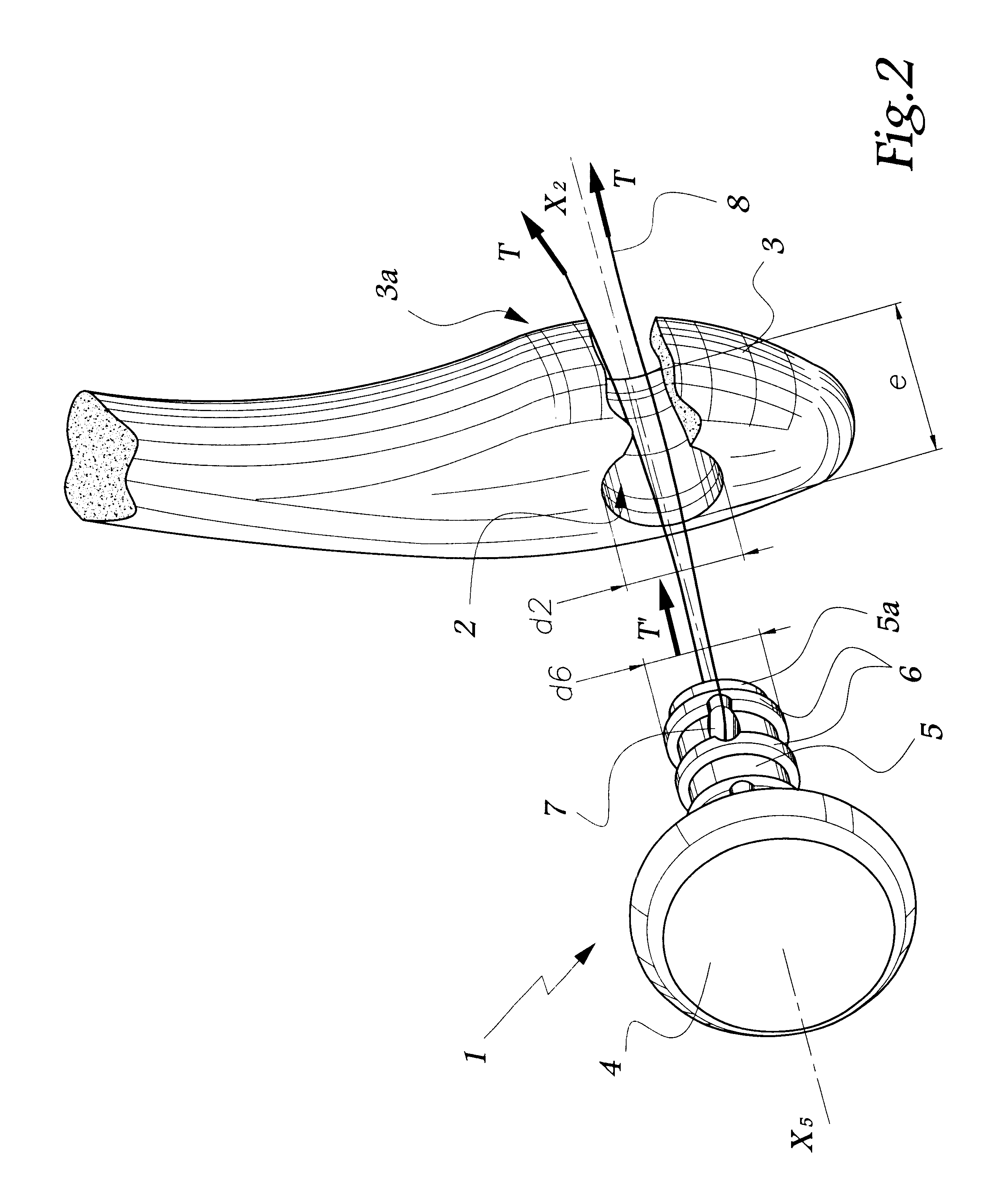
Referring now to the drawings, the implant 1 shown in FIGS. 1 and 2 is intended to be introduced in a bore 2 made in the lateral or fibular malleolus 3. The implant 1 comprises a convex head 4, substantially in the form of a spherical cap and of which the radius of curvature is substantially equal to that of the outer cheek of the astragalus of the ankle in question. The shank 5 of the implant 1 is provided with outer radial flanges 6 of which the outer diameter d.sub.6 is substantially equal to the inner diameter d.sub.2 of the bore 2.

According to the invention, two orifices 7 are provided in the shank 5 and are capable of receiving a suture thread 8 or other flexible tie. When such a thread is engaged in one of the orifices 7, it is possible to exert on the thread 8 an effort of T which is transmitted by the thread 8 to the shank 5 as represented by arrow T in FIG. 2. In this way, by pulling on the thread 8, the surgeon introduces the shank 5 in the bore 2 without having to exert ...


PUM


Abstract

A malleolar implant for partial or total ankle prosthesis which includes a head having a surface to bear against an astragalus or astragalian prosthetic component and from which head extends a shank adapted to be inserted through a bore in a fibula wherein the shank is provided with means for hooking a traction member which is adapted to be inserted through the bore in the fibula in order to apply a force to pull the implant into the bore such that the implant is seated within the bore of the fibula.

Description

The present invention relates to a malleolar implant for a partial or total prosthesis of the ankle and to an ancillary tool for placing, such an implant.DESCRIPTION OF THE RELATED ARTIt is known, for example from EP-A-0 864 304, to fit an ankle prosthesis with a malleolar implant intended to bear against an articular surface at the level of the astragalus, whether it be question of a natural surface or of a surface of a prosthetic component. During an operation on an ankle, access to the internal articular surfaces is limited by the ligamentary system which does not necessarily allow a sufficient dislocation of the joint. In particular, access to the internal surface of the fibular malleolus may be insufficient, which induces difficulties in positioning the implant, particularly by impaction.With reference to the embodiments of FIGS. 4 and 5, it is envisaged in EP-A-0 864 304 to introduce an implant from the outer face of the fibula. However, this necessarily limits the surface of ...

Claims


Application Information

Patent Timeline
Patent Type & Authority Patents(United States)
IPC IPC(8): A61B17/16A61B17/17A61F2/46A61F2/42A61F2/00A61F2/30
CPCA61B17/1739A61F2/4202A61F2/4606A61F2002/30224A61F2002/30299A61F2002/30785A61F2002/30878A61F2002/30879A61F2002/3096A61F2002/421A61F2230/0069A61F2230/0093
Inventor TORNIER, ALAINBONNIN, MICHELCOLOMBIER, JEAN-ALAINJUDET, THIERRY
Owner SMITH & NEPHEW INC
Why Eureka
Try Eureka