
Wiper bearing

a bearing and wing technology, applied in the field of wing bearings, can solve the problems of increasing wear on the casting tool, and achieve the effects of facilitating unmolding, reducing or largely avoiding the requisite post-machining of the bush seat, and facilitating installation

Inactive Publication Date: 2002-12-10
ROBERT BOSCH GMBH
View PDF6 Cites 11 Cited by
  • Summary
  • Abstract
  • Description
  • Claims
  • Application Information

AI Technical Summary

Benefits of technology

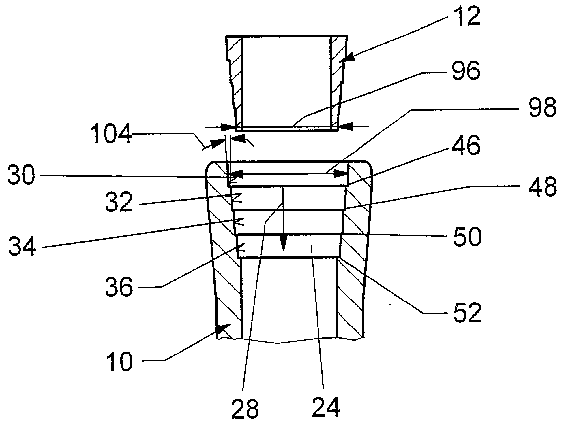
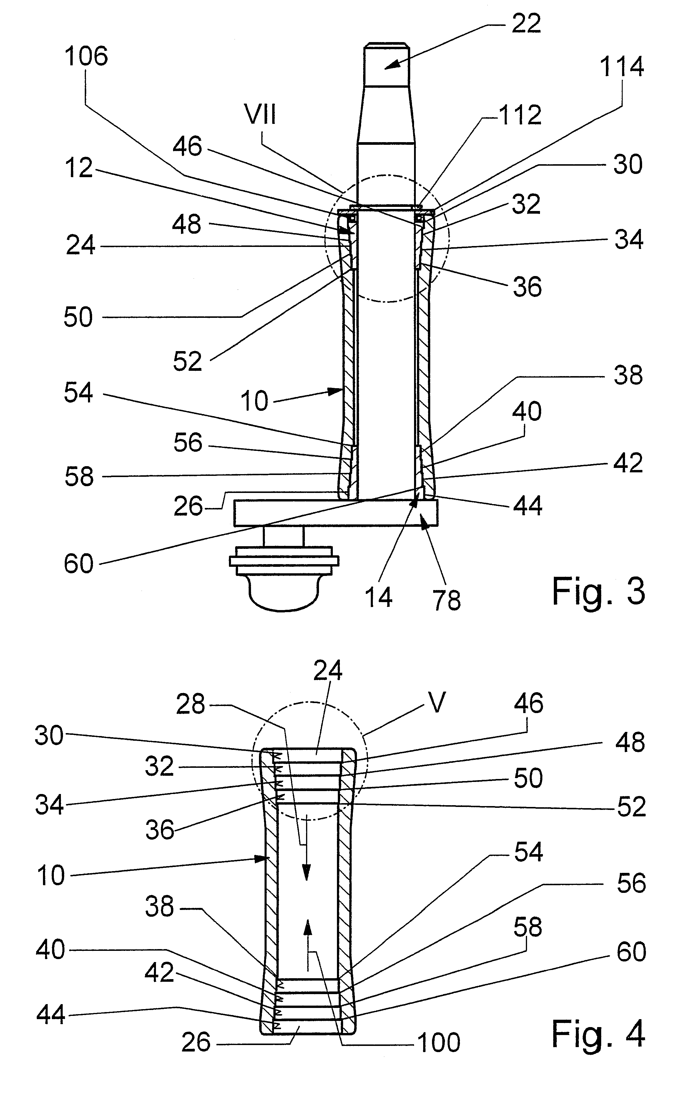
According to the invention, a bush seat of a bearing housing has at least two conical jacket faces, tapering in the mounting direction, which are preferably separated from one another by at least one radially inward-extending shoulder. With one or preferably more shoulders, despite steep, short jacket faces, a great change in diameter in the mounting direction of the bearing bush can be attained. As a result of the great change in diameter, a short joining distance of the bearing bush upon installation and a short unmolding distance of the bearing housing out of a casting tool are attained. When the bearing housing is removed from the casting tool, at first even after a short axial unmolding distance, faces of the casting tool are far away from the jacket faces of the bush seat. The unmolding is facilitated, and in particular wear of the casting tools and the requisite postmachining of the bush seat are reduced or largely avoided.
In the mounting or assembly process, first a small outer diameter of the bearing bush meets a large inside diameter of the bush seat, and only shortly before the bearing bush is fully introduced into the bush seat do jacket faces of the bearing bush come to rest, over a short joining distance, on the jacket faces of the bush seat. Installation is facilitated, and incorrect installation where the bearing bush is inserted with the wrong face end first is avoided. The jacket faces of the bush seat can be embodied steeply, with a requisite casting obliquity for unmolding of about 1.degree. to 2.degree. , despite a great change in diameter.
The drive shaft is driven by cranks and moves a wiper arm with a wiper blade over a windshield. This creates shear forces acting periodically on the drive shaft. The shear forces are supported via the bearing bush, the bearing housing, and the mounting plate on the vehicle body. Because of the conical faces between the bearing bush and the bearing housing, a force component counter to the mounting direction arises. However, with steep jacket faces, this force component is especially small, and the bearing bush remains reliably secured without play in the bearing housing. Also with steep jacket faces and an only slight mounting force, reliable self-locking is attained, and at even a small radially inward-oriented pressure onto the bearing bush, a secure, firm connection is made. The bearing bush largely retains its shape and especially its inside diameter, so that a drive shaft can easily be introduced into the bearing bush and guided exactly by it without play, without requiring major calibration effort or expense.
The bearing housing according to the invention of a wiper bearing having the stepped bush seat can be cast from zinc, plastic, or some other material thought suitable by one skilled in the art. Especially advantageously, however, the invention is employed with materials that are difficult to unmold, as in the case of bearing housings of aluminum or an aluminum alloy. Aluminum bearing housings are especially lightweight and rigid and can easily be unmolded with little wear from a casting tool, because of the short jacket faces and great change in diameter of the bush seat that are provided according to the invention. Postmachining of the bush seat is furthermore avoided largely or even completely.

Problems solved by technology

There is also increased wear on the casting tool.

Method used


Image

  • Wiper bearing
  • Wiper bearing
  • Wiper bearing

Examples


Embodiment Construction

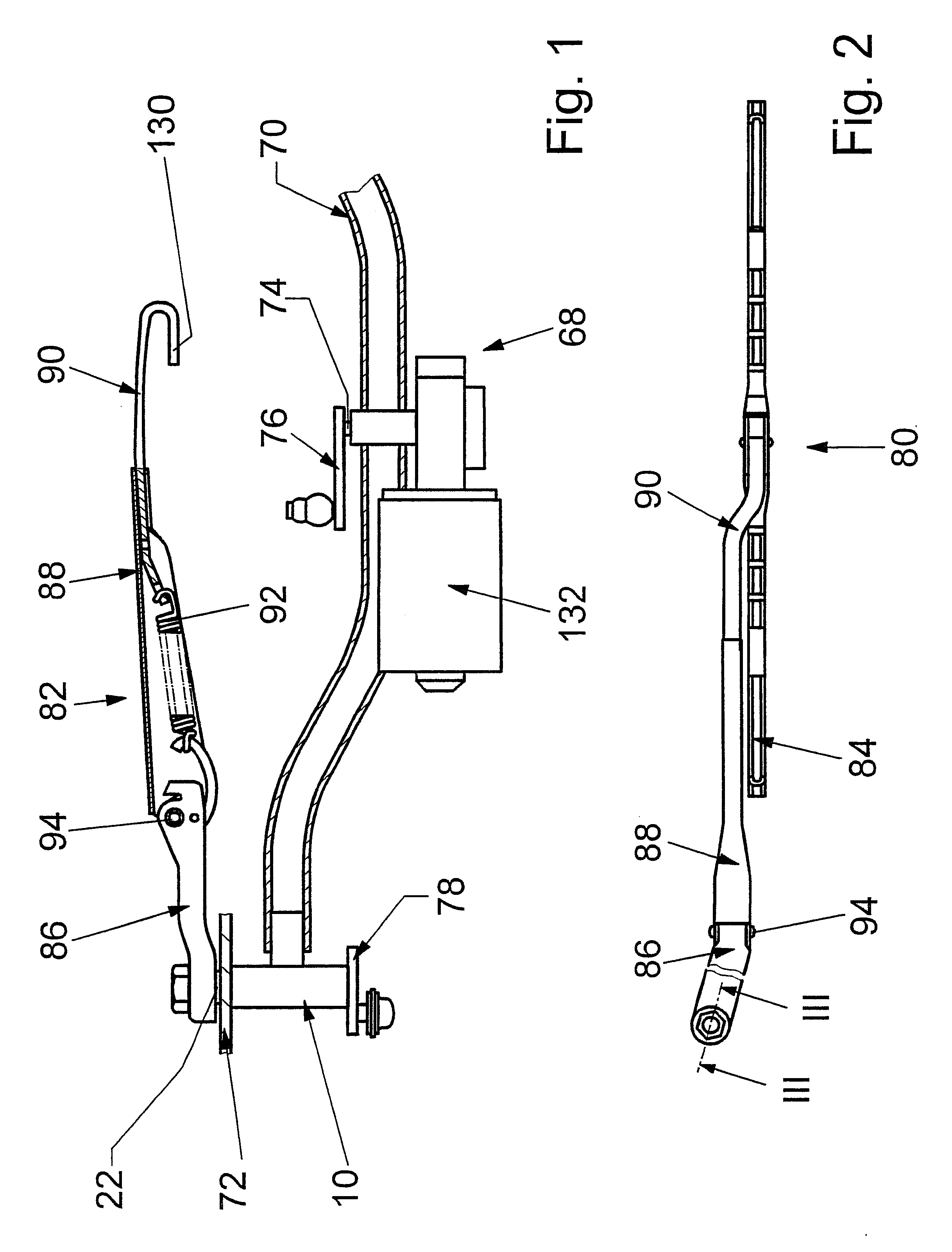
FIG. 1 shows a detail of a wiper system 68 for a motor vehicle, whose wiper bearings are fastened with a bearing housing 10 via a mounting plate 70 to a body 72 of the motor vehicle. The mounting plate 70 has a wiper drive mechanism with a wiper motor 132, whose motor shaft 74, via a crank 76 and a set of rods not shown in further detail, drives cranks 78 that are each solid connected to one end of a drive shaft 22 for a windshield wiper 80. The drive shaft 22 is radially and axially supported in the bearing housing 10, protrudes from the body 72, and moves a wiper arm 82, which is secured to its free end and has a wiper blade 84, over a windshield (FIG. 2). The wiper arm 82 has a fastening part 86, which is connected to the drive shaft 22 and is connected pivotably via a toggle joint 94 to a hinge part 88, which is rigidly adjoined by a wiper rod 90. The wiper blade 84 is suspended from a bracketlike end 130 in the wiper rod 90. A requisite contact pressure of the wiper blade 84 on...


PUM


Abstract

The invention is based on a wiper bearing, having a bearing housing (10) in which at least one bearing bush (12, 14, 16, 18, 20) for a drive shaft (22) is disposed in a bush seat (24, 26).It is proposed that the bush seat (24, 26) has at least two conical jacket faces (32, 34, 36, 38, 40, 42, 44), which taper in the mounting direction (28, 100), which are separated from one another by at least one radially inward-extending shoulder (46, 48, 50, 52, 54, 56, 58, 60), of the bearing bush (12, 14, 16, 18, 20), and the bearing bush (12, 14, 16, 18, 20) has an outer contour corresponding to the contour of the bush seat (24, 26).

Description

PRIOR ARTThe invention is based on a wiper bearing.Wiper systems with multiple windshield wipers for motor vehicles are fastened with their wiper bearings directly or indirectly to a body of the motor vehicle, via a mounting plate. The mounting plate has a wiper drive mechanism with a wiper motor, whose motor shaft, via a set of rods, drives cranks that are solidly joined to one end of a drive shaft for each windshield wiper. It is also possible for only the drive shaft of one windshield wiper to be driven by the wiper motor, while another windshield wiper is connected to the first windshield wiper via a four-bar lever mechanism and has a bearing axis. The drive shaft or bearing axis is supported in a wiper bearing. The remarks hereinafter will be made with regard to a drive shaft for a bearing axis that will no longer be mentioned expressly.At least one radial bearing is provided in the bearing housing, and on the face ends between the bearing housing and a part solidly joined to t...

Claims


Application Information

Patent Timeline
Patent Type & Authority Patents(United States)
IPC IPC(8): B60S1/34B60S1/32B60S1/04F16C33/08F16C33/04
CPCB60S1/04B60S1/0419B60S1/34B60S1/3493F16C33/08F16C2326/09
Inventor ZIMMER, JOACHIM
Owner ROBERT BOSCH GMBH
Learn More