AI technical title is built by Patsnap AI team. It summarizes the technical point description of the patent document.
a gas-cylinder pistol and multi-charge technology, which is applied in the direction of ammunition loading, weapon components, white arms/cold weapons, etc., can solve the problems of shortened service life of the striker mechanism, low reliability and shooting rate of these constructions, and limited shape and material limitations, so as to improve the functional potentiality, increase the performance characteristics of the pistol, and improve the reliability.
Inactive Publication Date: 2002-12-17
ZAKRYTOE AKTSIONERNOE OBSHCHESTVO GRP ANICS
View PDF28 Cites 83 Cited by
Summary
Abstract
Description
Claims
Application Information
AI Technical Summary
This helps you quickly interpret patents by identifying the three key elements:
Problems solved by technology
Method used
Benefits of technology
Benefits of technology
The present invention is directed to the provision of a repeating gas cylinder pistol with such structural elements and connections therebetween, that would make it possible to increase substantially the reliability, to improve and broaden the functional potentialities, and to raise the performance characteristics of the pistol.
In the upper part of the body of the valve opposite the magazine a ring-shaped saddle is provided, inside which a hollow cylinder of the valve is located, the end face part of the cylinder enters the cutout in the upper part of the cover of the magazine and abuts against the flat leaf spring which limits from the front the travel of the valve with the cylinder, the valve installed coaxially with the bullet bore of the barrel and with a throttle opening in the leaf spring being in the closed state, when the spring is extended and the valve is pressed to the saddle or makes up a clearance with the saddle, when after a short-time action of the leaf spring on the cylinder of the valve the spring is compressed, for a portion of gas to come from the gas chamber to the cylinder of the valve. Between the saddle and the valve an annular cup is disposed, which precludes coming of a portion of gas to the cylinder when the valve is closed. Between the body of the valve and the saddle in an annular groove provided on the side of the saddle which adjoins the body a seal is disposed, which precludes gas leakage from the gas chamber.
The pistol has a rod which with its one end, having a cylindrical head whose diameter is greater than the cross-section of the rod, is installed in a depression provided in the base of the support under the upper front projection parallel to the axis of the cylinder, a return spring being located on the rod between the head and the inner side of the front wall of the breech block, the return spring being compressed when the breech block is installed on the pistol frame, the other end of the rod being disposed in a lower opening on the front wall of the breech block, ruling out casual jumping of the breech block off the pistol frame.
Problems solved by technology
However, the reliability and shooting rate of these constructions are low.
In spite of a number of advantages, such as the possibility of shooting with the movable barrel of the pistol in any position, even in the direction of action of the Earth's attraction force, and an increased shooting rate by combining the operations of winding the mainspring and introducing the ball bullet into the barrel only on pulling the trigger of the pistol, the above-described construction has a number of disadvantages: limitations to the shape and material of bullets, since the in the above-described construction it is possible to use only ball steel or steel-core bullets; shortened service life of the striker mechanism because of constant mechanical effect of the barrel on the valve at the moment of shooting; a small capacity of the magazine; a low reliability, because the process of feeding bullets to the shooting position is not controllable, the probability of a misfire being thus increased, and because a shot may be taken even in the absence of the magazine in the pistol grip.
Method used
Image
Click on the blue label to locate the original text in one second.
Reading with bidirectional positioning of images and text.
Examples
Embodiment Construction
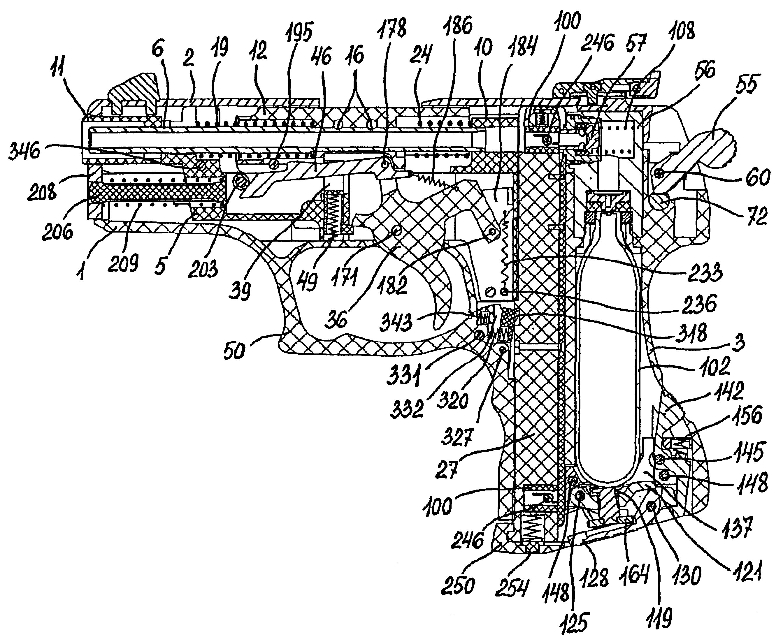
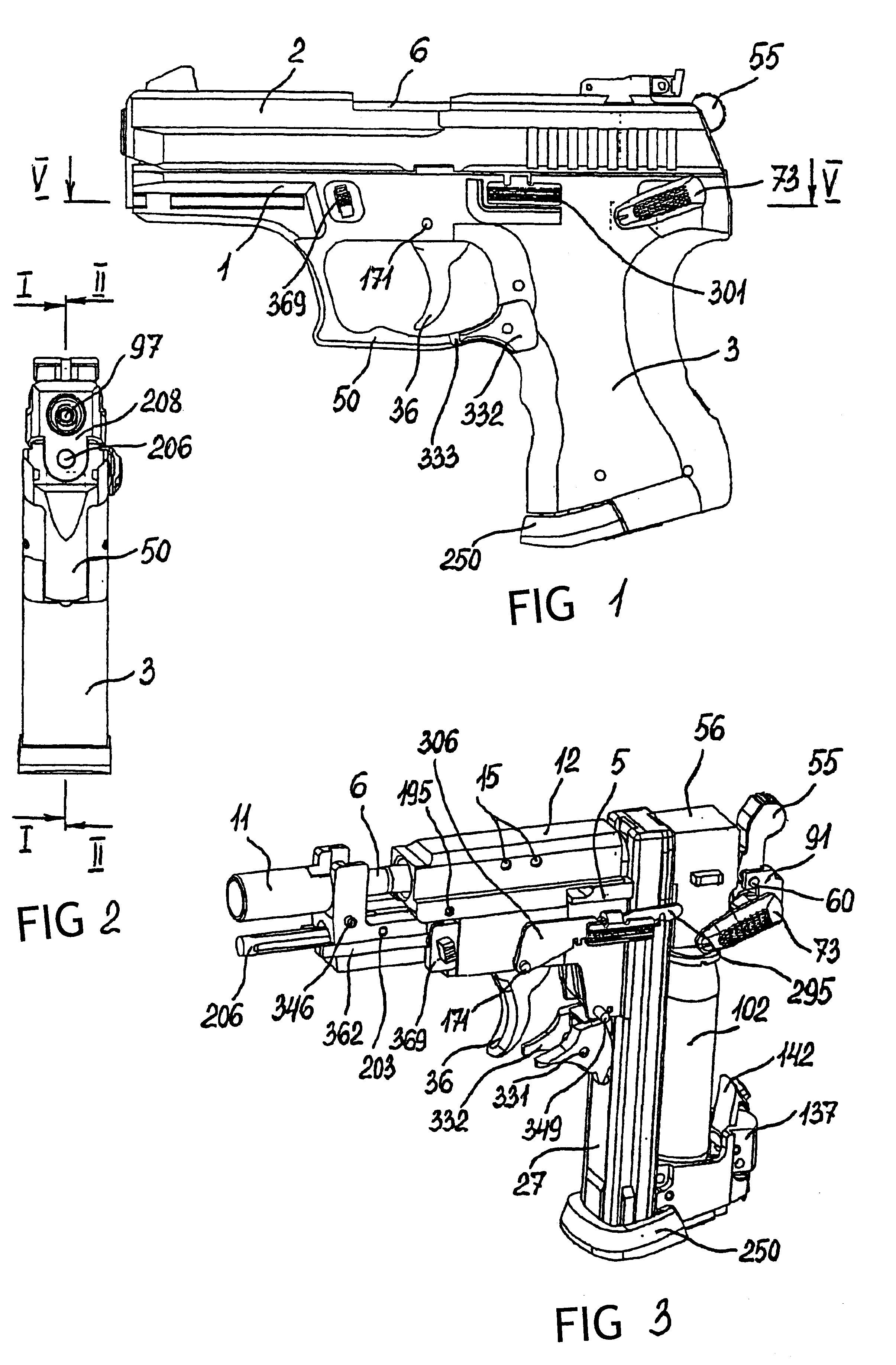
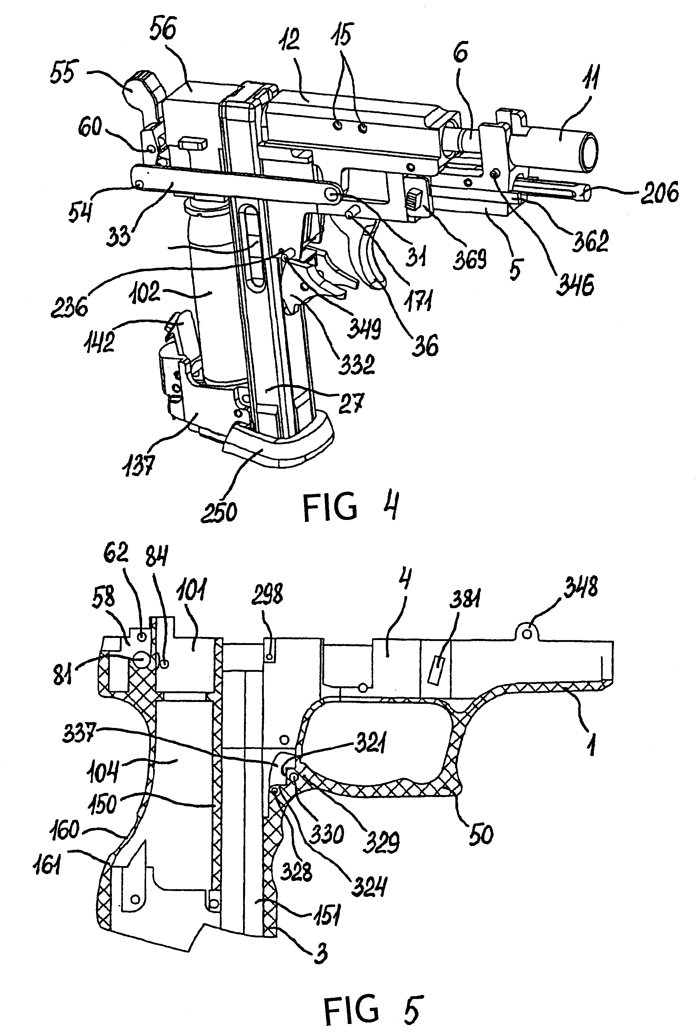
A repeating gas cylinder pistol (FIGS. 1-4), embodied according to the invention, comprises a hollow pistol frame 1 (FIGS. 5, 6) with a pistol breech block 2 (FIGS. 7, 8) the lower part of the pistol frame 1 being a grip 3 of the pistol. In a hollow interior 4 (FIG. 6) of the pistol frame 1 (FIGS. 9, 10) under the breech block 2 a support 5 is installed (FIGS. 11-13). The support 5 serves as a base for a movable barrel 6 that moves relative thereto. The barrel 6 moves along a front pilot cylindrical hole 7 and a rear pilot cylindrical hole 8 located in an upper front projection 9 and a lower projection 10, respectively, and in the rear part of a cylinder 11 of the support 5, disposed in front of the upper front projection 9.
On the barrel 6 a load 12 is located (FIGS. 14, 15), which, owing to the provision in the middle part thereof of a through longitudinal opening 13 whose diameter coincides with the outer diameter of the barrel 6, proves to be set onto the barrel 6. The load 12, t...
PUM
Abstract
The present invention relates to compressed gas-operated firearms and more particularly to repeating gas cylinder pistols with conveyer feed of bullets for shooting. The pistol comprises a hollow pistol frame (1) made integral with a grip (3) and a trigger bow (50), a movable barrel (6) with a bullet bore (97), a load (12) and a mainspring (19) disposed on the barrel (6), a valve (57) installed in a gas chamber (110) inside a body (56), a gas cylinder (102) installed inside a rear hollow interior (104) of the grip (3), a magazine (27) installed in a front hollow interior (151) of the grip (3), separated from a rear hollow interior (104) by a partition (150), a striker-and-trigger mechanism installed inside the pistol frame (1) and on the trigger bow (50) and interacting with the movable barrel (6) and the magazine (27) for supplying bullets (246) and portions of gas from the gas cylinder (102) to the bullet bore (97) of the barrel (6), a mechanism for installing the gas cylinder (102), disposed below the gas cylinder (102) in the grip (3). In a hollow interior (4) of the pistol grip (1) a support (5) is installed, which serves as a base for the movable barrel (6) that moves along the support (5) under the action of the striker-and-trigger mechanism.
Description
FIELD OF THE ARTThe present invention relates to compressed gas-operated firearms and more particularly to repeating gas cylinder pistols with conveyer feed of bullets for shooting.STATE OF THE ARTKnown in the art are technical solutions of a repeating gas cylinder pistol shooting ball bullets: U.S. Pat. No. 3,077,875, Cl. 124-11, 1963; U.S. Pat. No. 3,207,143, Cl. 124-11, 1965; U.S. Pat. No. 3,447,527, Cl. 124-52, 1969; U.S. Pat. No. 3,527,194, Cl. 124-11, 1970; U.S. Pat. No. 4,147,152, Cl. 124-76, 1979; Patent EP 0,625,689, 1994; Patent RU 2,084,802, Cl. 6F41B Nov. 6, 1997. However, the reliability and shooting rate of these constructions are low.The prior art most relevant to the present invention is a repeating gas cylinder pistol shooting ball bullets (Patent RU No. 2,118,781, Cl. F41B Nov. 6, 1998), comprising a pistol frame with a grip, a movable barrel with an opening for introducing bullets and with a load and a mainspring located thereon between the load and a slider base ...
Claims
Application Information
Patent Timeline
Application Date:The date an application was filed.
Publication Date:The date a patent or application was officially published.
First Publication Date:The earliest publication date of a patent with the same application number.
Issue Date:Publication date of the patent grant document.
PCT Entry Date:The Entry date of PCT National Phase.
Estimated Expiry Date:The statutory expiry date of a patent right according to the Patent Law, and it is the longest term of protection that the patent right can achieve without the termination of the patent right due to other reasons(Term extension factor has been taken into account ).
Invalid Date:Actual expiry date is based on effective date or publication date of legal transaction data of invalid patent.

