
Fluidic nozzle with multiple operating modes

a technology of fluid nozzle and operating mode, which is applied in the direction of combustion types, transportation and packaging, lighting and heating apparatus, etc., can solve the problem of filling the oscillating circui

Inactive Publication Date: 2002-12-24
DLHBOWLES INC
View PDF6 Cites 125 Cited by
  • Summary
  • Abstract
  • Description
  • Claims
  • Application Information

AI Technical Summary

Benefits of technology

In many nozzle applications where liquid such as water is being projected into a hot tub spa, it is desirable that the liquid spray nozzle issue a spray which oscillates between a certain included angle between the extreme positions of the jet for massaging effect and also that the jet of liquid used (water) be mixed with emollients or other operating liquids in one mode of operation, and in another mode of operation that air be entrained with the water.

Problems solved by technology

An outlet is provided at the downstream end of the oscillation chamber and has a width which does not allow the oscillation circuit to fill up and start oscillation without entrained liquid.

Method used


Image

  • Fluidic nozzle with multiple operating modes
  • Fluidic nozzle with multiple operating modes
  • Fluidic nozzle with multiple operating modes

Examples


Embodiment Construction

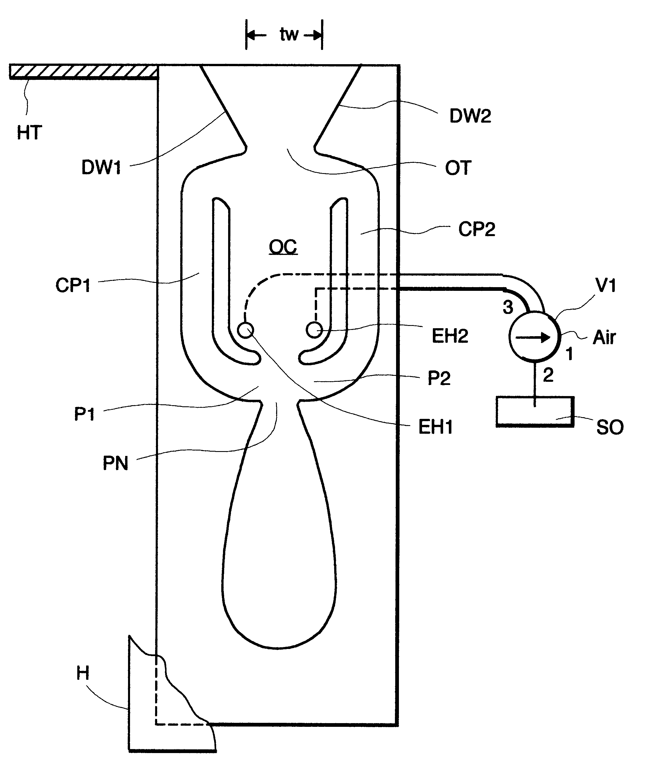
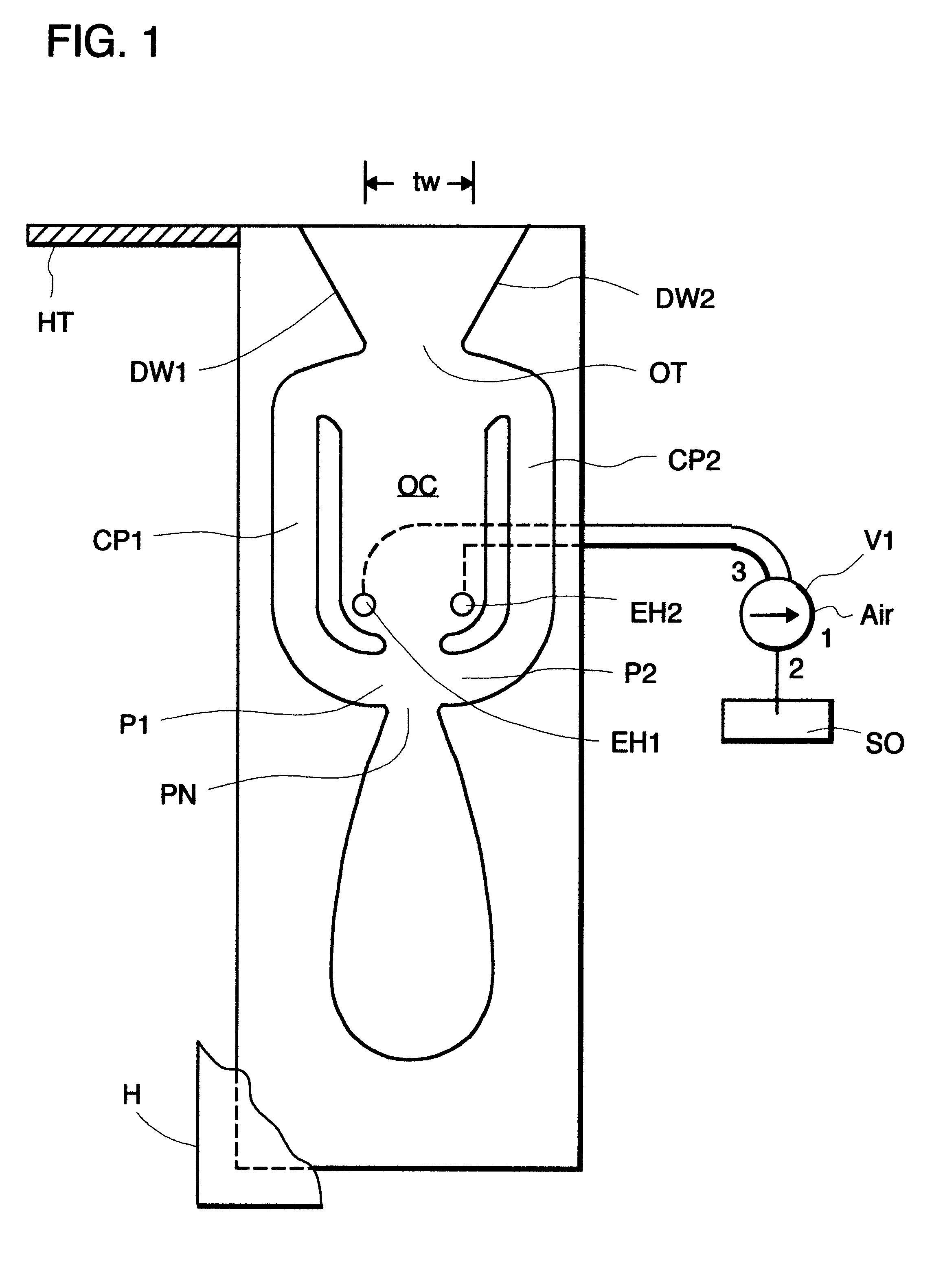
Referring to FIG. 1, the fluidic nozzle with dual operating modes is disclosed as having an oscillation chamber OC with an upstream end and a downstream end with a power nozzle PN at the upstream end for issuing a jet of liquid into the oscillation chamber OC and is connected to a source (not shown) of water under pressure. The downstream end is provided with an outlet throat OT with diverging sidewalls DW1, DW2. The throat width TW is such as to not allow the circuit to fill up with liquid to start to oscillate. A pair of entrainment holes EH1, EH2 is provided for entrainment of air or liquid emollients or chemicals.

A pair of control ports P1, P2 are provided adjacent the power nozzle PN, and a pair of control passages CP1, CP2 for feeding back control signals to the control ports CP1, CP2, respectively. A housing H is shown partially removed for clarity.

The entrainment holes EH1, EH2 are coupled through a valve member V1 to (1) air or (2) to a source SO of liquid or chemical emoll...


PUM


Abstract

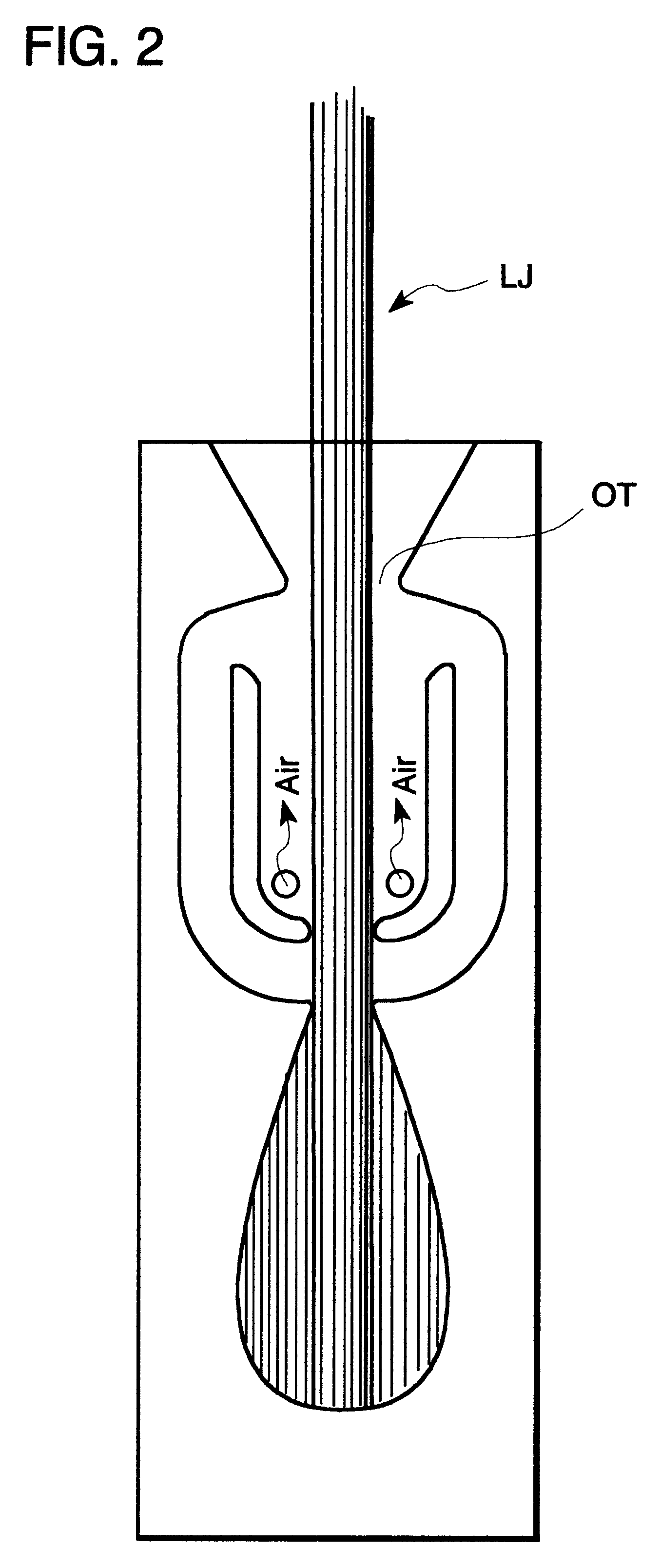
A fluidic nozzle having multiple operating modes comprising a fluidic oscillator circuit having an oscillation chamber having an upstream end and a downstream end and a power nozzle at the upstream end for introducing a jet of a liquid (water) into the oscillation chamber. An outlet throat at the downstream end has a width, which does not allow the oscillation circuit to fill up and start to oscillate without entrained liquid. A pair of control ports are at the upstream end of the oscillation chamber and a pair of feedback passages connect said control ports to downstream ends of said oscillation chamber adjacent said outlet throat. A pair of controllable entrainment holes are provided in the oscillation chamber at the upstream end and a valve opens and closes the entrainment holes, such that when the entrainment holes are open to air, air is entrained and the oscillator does not oscillate. Closing the air entrainment holes initiates oscillation and the issuance of a sweeping liquid jet through the outlet throat.

Description

BACKGROUND AND BRIEF DESCRIPTION OF THE INVENTIONIn many nozzle applications where liquid such as water is being projected into a hot tub spa, it is desirable that the liquid spray nozzle issue a spray which oscillates between a certain included angle between the extreme positions of the jet for massaging effect and also that the jet of liquid used (water) be mixed with emollients or other operating liquids in one mode of operation, and in another mode of operation that air be entrained with the water.The present invention provides a fluidic nozzle having multiple operating modes wherein a fluidic oscillator circuit having an oscillation chamber with an upstream end and a downstream. A power nozzle is positioned at the upstream end for introducing a jet of liquid such as water into the oscillation chamber. An outlet is provided at the downstream end of the oscillation chamber and has a width which does not allow the oscillation circuit to fill up and start oscillation without entrai...

Claims


Application Information

Patent Timeline
Patent Type & Authority Patents(United States)
IPC IPC(8): A61H33/00B05B1/02B05B1/08
CPCA61H33/6057B05B1/08A61H33/0087Y10S239/07Y10S239/03Y10T137/206Y10T137/2185Y10T137/2224
Inventor SRINATH, DHARAPURAM N.BURNS, SEAN T.
Owner DLHBOWLES INC
Learn More