Slide rod locking device

a technology of sliding rods and locking devices, which is applied in the direction of carpet fasteners, wing knobs, dwelling equipment, etc., can solve the problems of restricted spatial conditions and structural size of sliding rod locking devices

Inactive Publication Date: 2002-12-24
RITTALWERK RUDOLF LOH GMBH & CO KG
View PDF8 Cites 23 Cited by
  • Summary
  • Abstract
  • Description
  • Claims
  • Application Information

AI Technical Summary

Problems solved by technology

But this causes the sliding rod locking device to have a structural size which is interfering when used with a switchgear cabinet.
A sliding rod designed in this way requires only little space and thus takes restricted spatial conditions into consideration.

Method used


Image

  • Slide rod locking device
  • Slide rod locking device
  • Slide rod locking device

Examples


Embodiment Construction

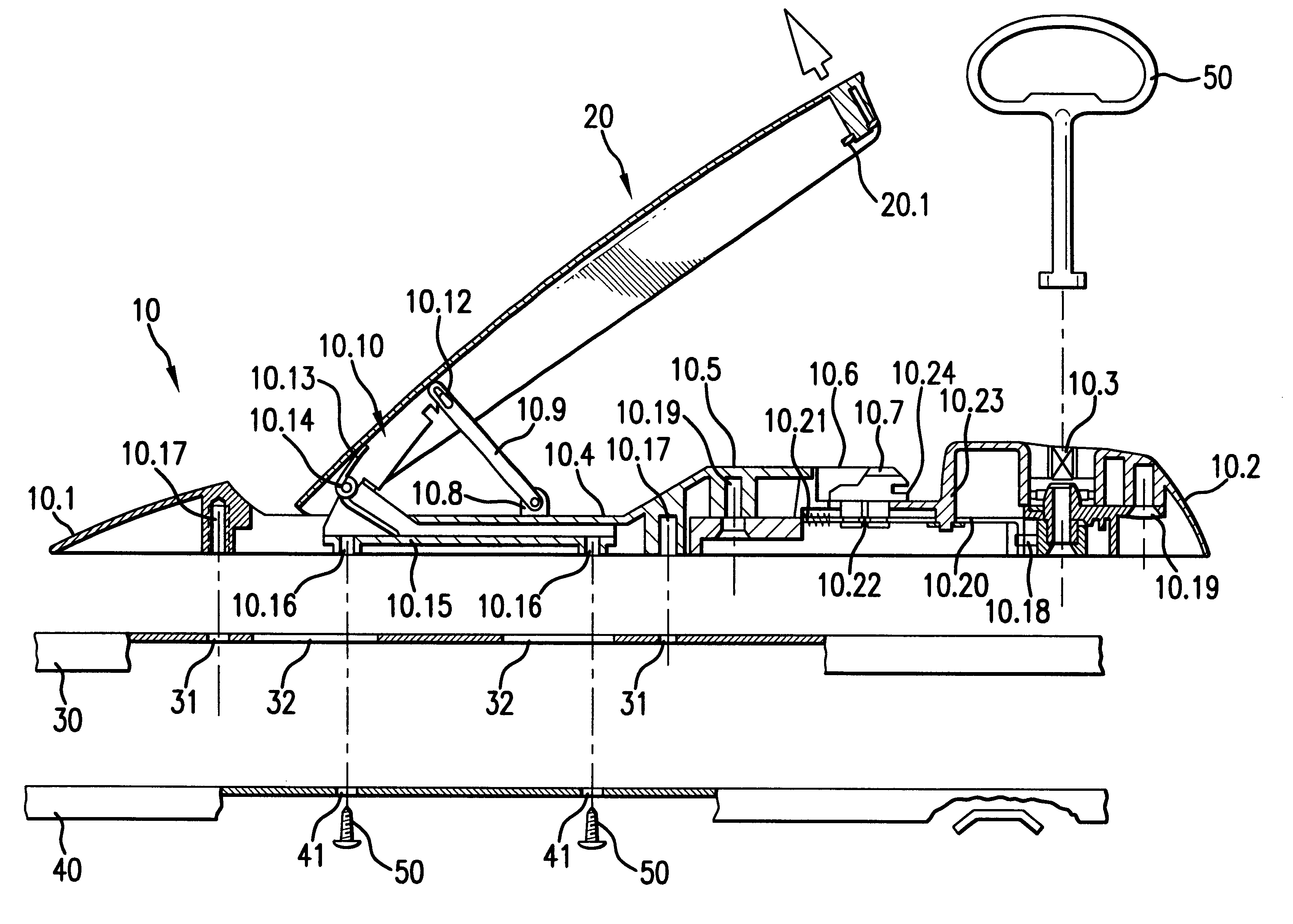
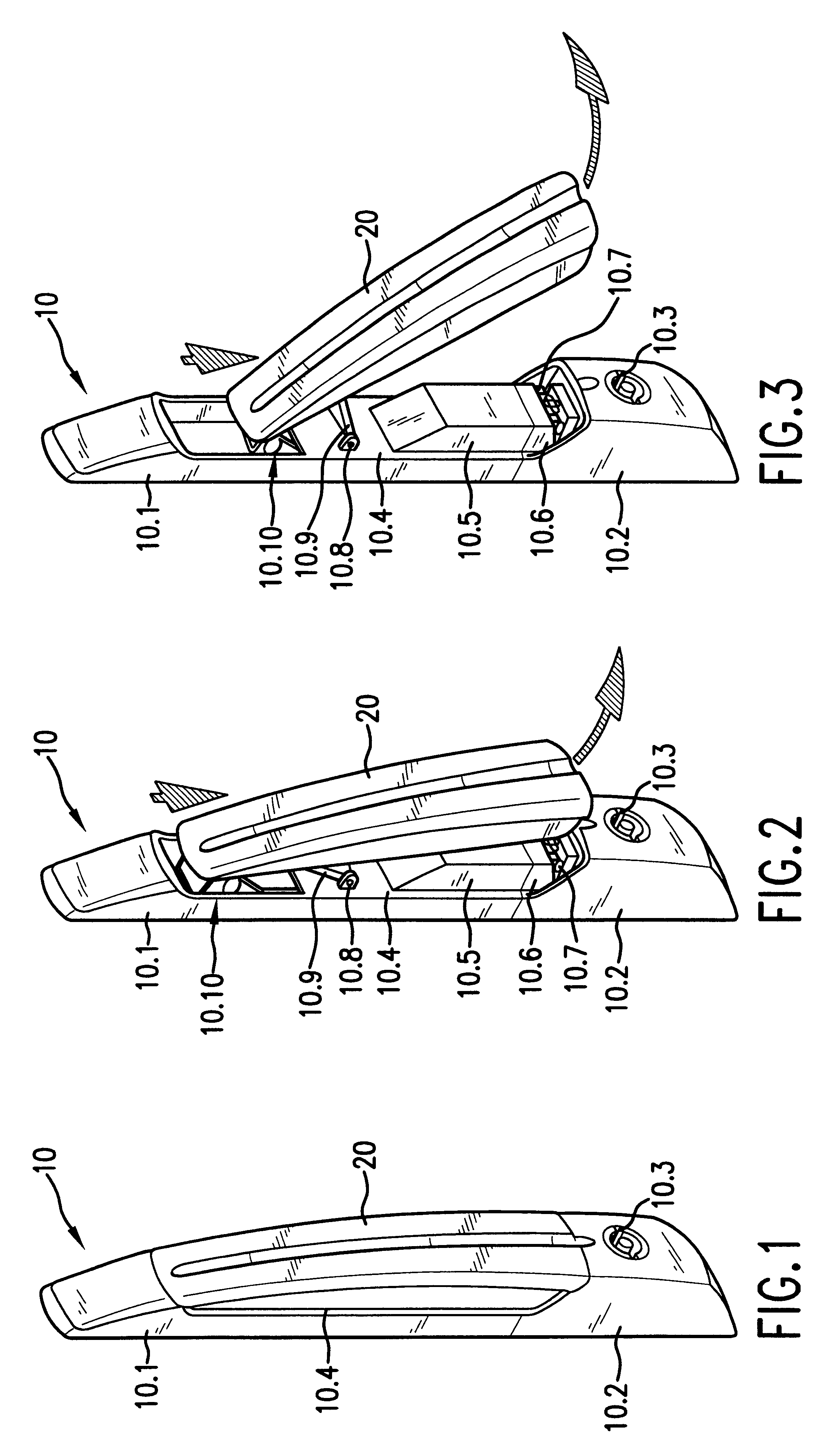
A sliding rod locking device, which has a housing 10 with a handle recess 10.4 is shown in FIG. 1. The housing 10 is made of two parts comprising a base housing 10.1 and an attachment housing 10.2. With the attachment housing 10.2 installed, the base housing 10.1 and the attachment housing 10.2 together form the handle recess 10.4. A handle 20 is housed in the handle recess 10.4. FIG. 1 shows that in a pivoted-in condition the handle 20 is received within the handle recess 10.4 and with its surface flush with the housing 10. The attachment housing 10.2 receives a lock 10.3.

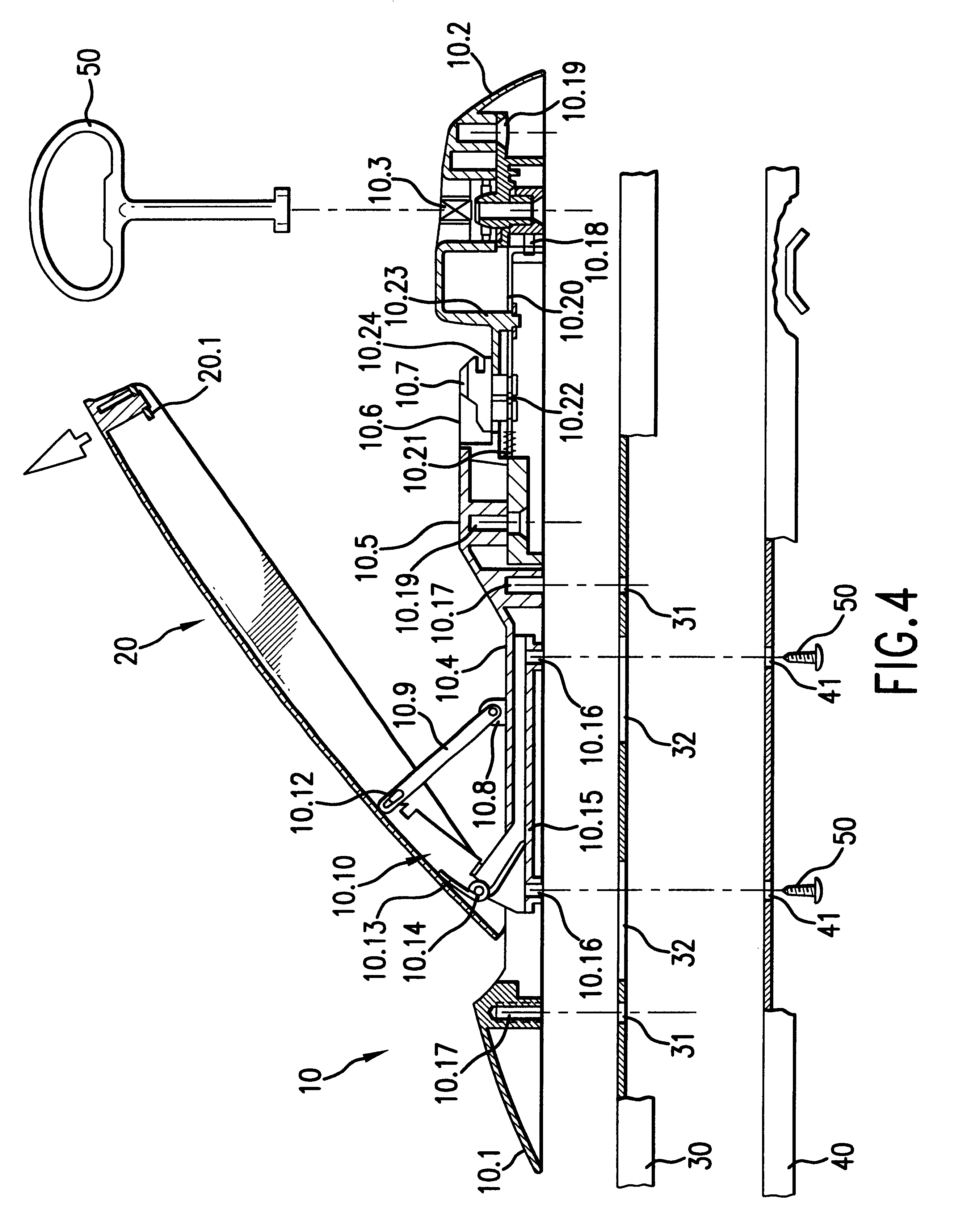
A sliding rod locking device in accordance with FIG. 1 is shown in FIG. 2 wherein, however, the handle 20 is partially pivoted out of the handle recess 10.4. As shown, the handle 20 is connected with the housing 10 via an actuating mechanism 10.10. The functioning of the actuating mechanism 10.10 will be explained later, making reference to FIG. 4.

A bolt 10.7, which is housed in a bolt receptacle 10.6, is used for...


PUM


Abstract

A slide rod locking system, especially for locking the door of a switchgear cabinet, having a handle which is coupled to a control element by a control mechanism. The handle can move around a pivotal axis running perpendicular to the plane of the cabinet door. The control element can move in a parallel position relative to the plane of the cabinet door as a result of the movement of the handle. The slide rod locking system transmits powerful locking forces and at the same time can have a low-height design structure by arranging a lever on an articulated joint of the handle at a distance from the pivotal axis. The lever enables the force introduced into the handle to be transmitted to the control element and can modify its angle position with respect to the handle when moved.

Description

1. Field of the InventionThis invention relates to a sliding rod locking device for locking a cabinet door of a switchgear cabinet, having a handle, to which an actuating mechanism is connected via an actuating mechanism, wherein the handle can be adjusted in a pivot plane extending vertically with respect to the plane of the cabinet door, and by displacement of the handle, the actuating member can be displaced parallel with respect to the plane of the cabinet door.2. Description of Related ArtA sliding rod lock used for locking emergency exit doors is known from German Patent Reference DE 77 23 134. A handle is seated, pivotal around a horizontal axis, in a housing. The handle has a manipulating device facing the user on the front of the housing. A lever is formed on the handle remote from the manipulating device. An actuating member is connected to the lever and is linearly displaceable in the housing. The actuating member has teeth, which mesh with a gear wheel. A second actuatin...

Claims


Application Information

Patent Timeline
Patent Type & Authority Patents(United States)
IPC IPC(8): E05C9/00E05C9/02E05B1/00E05B13/00E05C9/04E05B5/00E05B5/02H05K5/03
CPCE05C9/02E05B1/0092E05B5/003E05B13/002E05C9/046Y10S292/53Y10T292/0845Y10T292/1015Y10T292/57
Inventor MUNCH, UDOREUTER, WOLFGANG
Owner RITTALWERK RUDOLF LOH GMBH & CO KG
Why Eureka
Try Eureka