Dynamic duty cycle adjuster

a technology of duty cycle and adjuster, which is applied in the direction of pulse generator, pulse manipulation, pulse technique, etc., can solve the problems of different problems in the accuracy of clock signals, clock skew becomes an ever-increasing problem, and tolerances are necessarily diminished

Inactive Publication Date: 2002-12-31
LINKEDIN
View PDF8 Cites 47 Cited by
  • Summary
  • Abstract
  • Description
  • Claims
  • Application Information

AI Technical Summary

Benefits of technology

It is another object of the present invention to provide an improved clock distribution network which reduces duty cycle variations.
It is yet another object of the present invention to provide such an improved clock distribution network which dynamically adjusts the duty cycle without adding significant expense.

Problems solved by technology

As clock circuits improve and clock rates increase, tolerances are necessarily diminished, and clock skew becomes an ever-increasing problem.
Different problems can arise in the accuracy of the clock signal.
These networks can introduce duty cycle distortion due to circuit and interconnect modeling inaccuracies, process variations, and the environment.
For systems which use both the rising and falling edges for timing, a non-optimal clock duty cycle may require a lower clock frequency, reducing performance.
A duty cycle error of just 5% for instance (from 50% to 45%) may require a system clock to run at a maximum speed that is 10% lower, causing a significant impact on system performance.
Actual duty cycles typically do not have precisely the desired value.
All of the foregoing techniques add a new level of complexity to the clock distribution scheme.
All of these techniques also apply to bulk semiconductor technology, and may be unsuitable for other fabrication methodologies, such as a silicon-on-insulator (SOI) process.

Method used


Image

  • Dynamic duty cycle adjuster
  • Dynamic duty cycle adjuster
  • Dynamic duty cycle adjuster

Examples


Embodiment Construction

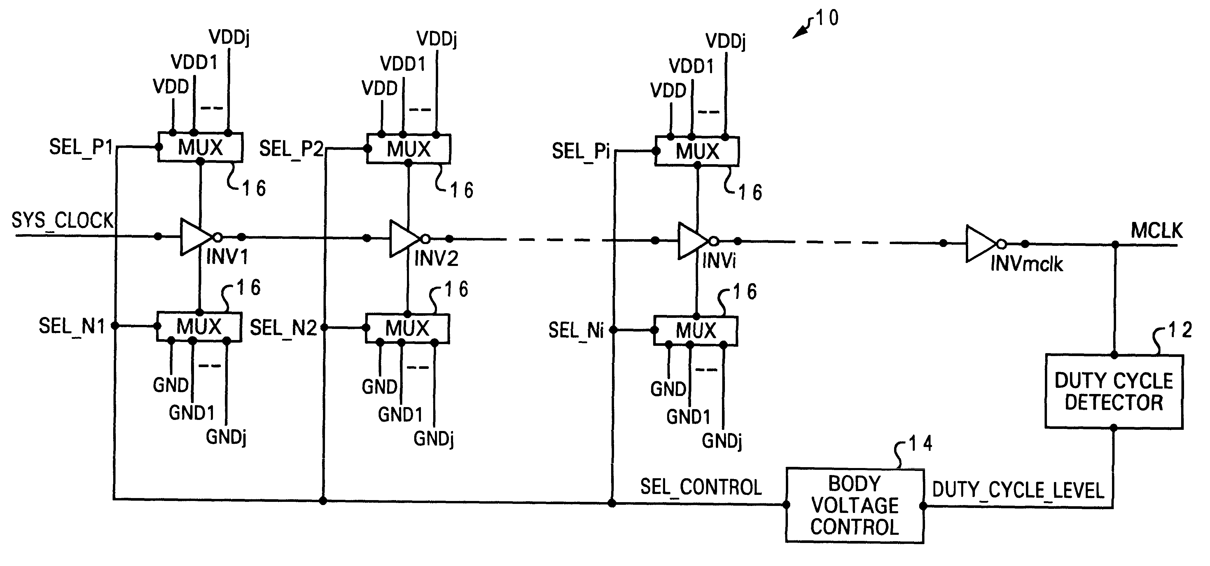
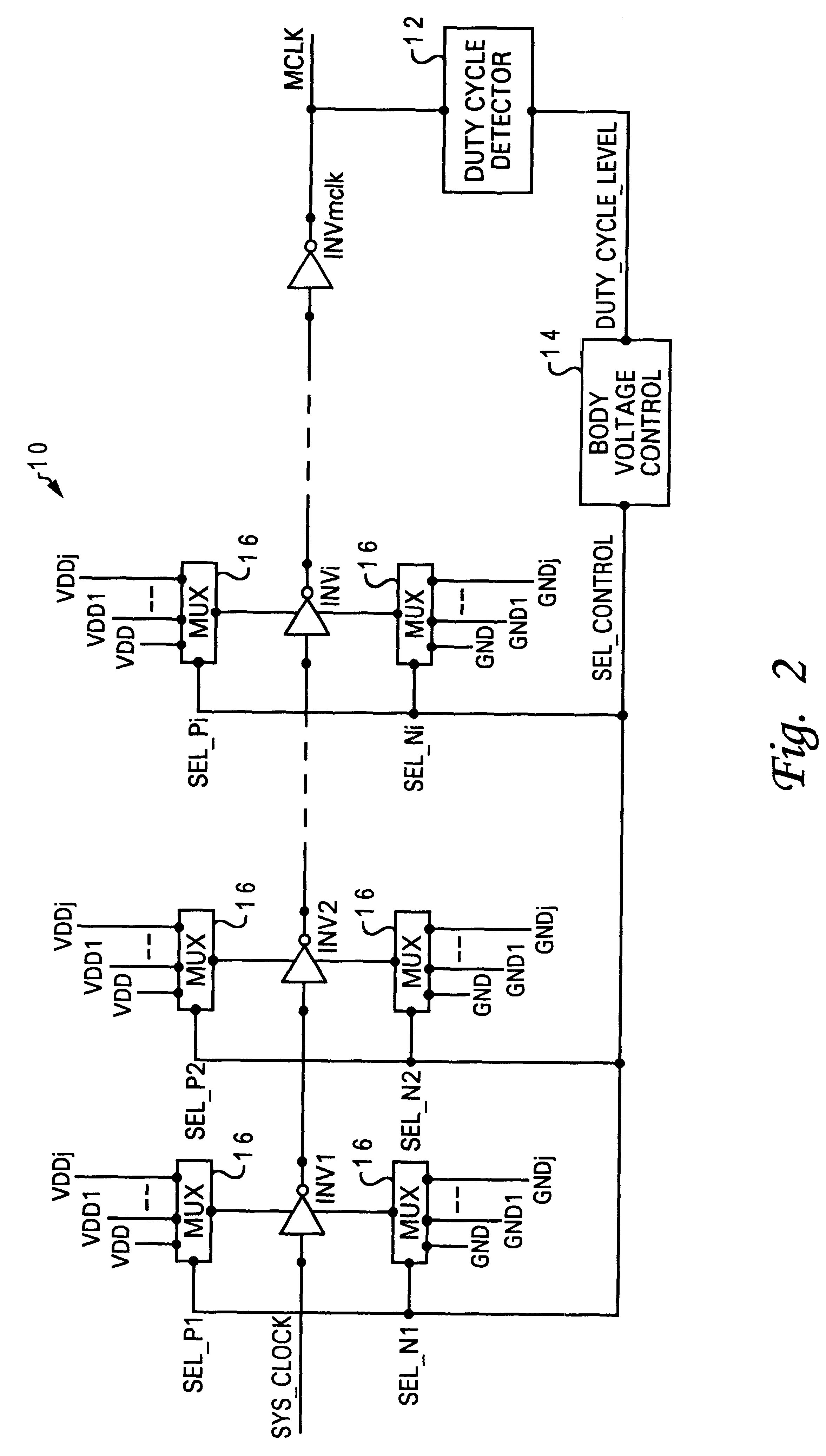
The present invention is directed to a novel method and system for dynamically adjusting the duty cycle of a clock signal in a clock distribution network. The body voltage of a device (or group of devices) in the clock distribution network is manipulated to adjust the duty cycle of a microprocessor system clock which has deteriorated from its desired value (e.g., 50%) after going through the clock distribution network.

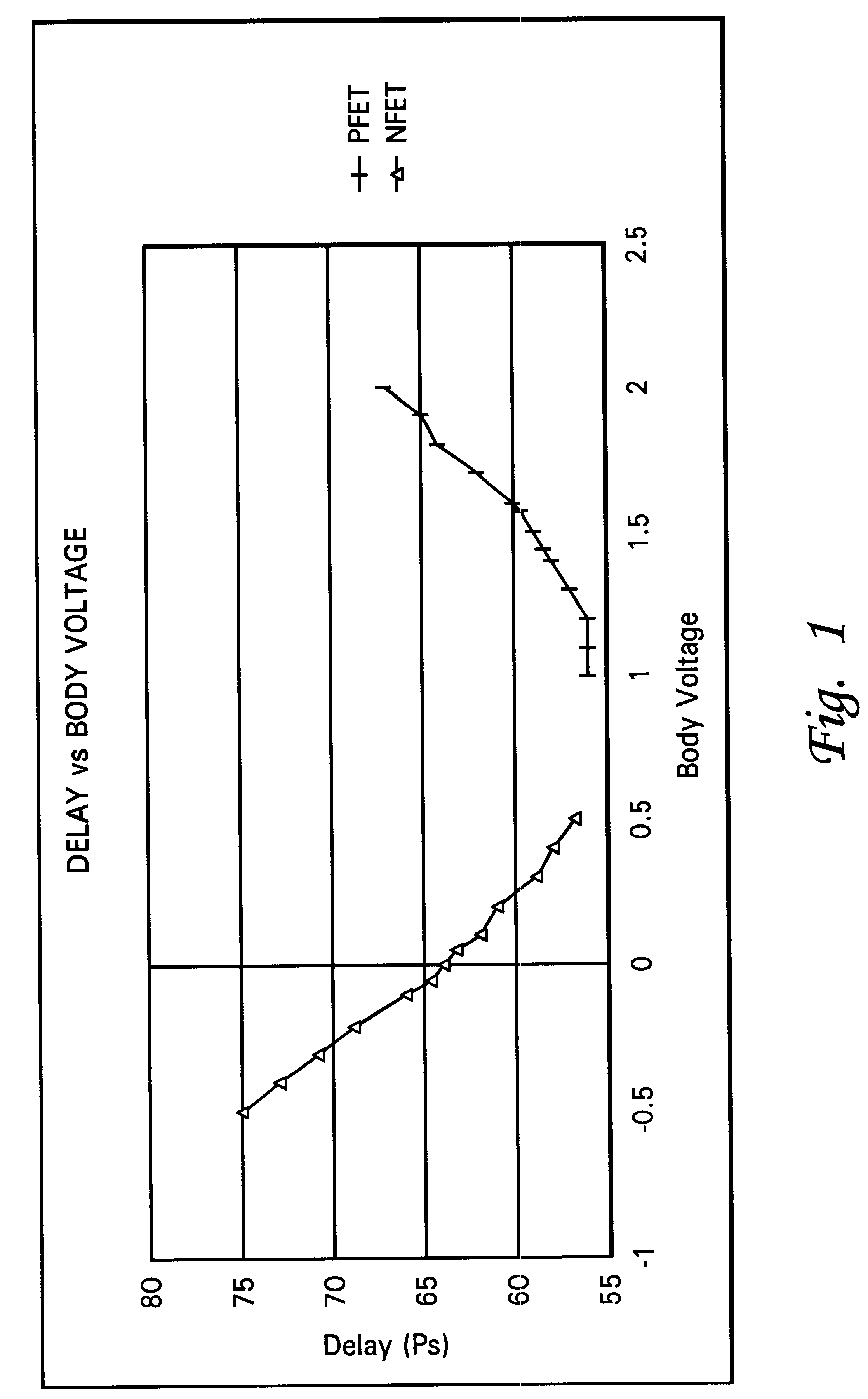
Reducing the body voltage of a p-type field-effect transistor (PFET) with respect to its supply voltage (V.sub.dd) reduces the magnitude of the threshold voltage for the device, causing its conduction state to begin earlier when it is switched from OFF-to-ON, and also causing the conduction state to persist longer when the device is switched from ON-to-OFF. The threshold voltage of an n-type field-effect transistor (NFET) is reduced when its body voltage is increased with respect to electrical ground, exhibiting the same kind of conduction state stretching / shrinking ph...


PUM


Abstract

A method of controlling a clock signal in a clock distribution network, by detecting an error in a duty cycle of the clock signal, and dynamically adjusting the body voltage of one or more devices in the clock distribution network, based on the detected error. Where the electronic device is a p-type device, the adjustment may be performed by reducing the body voltage of the p-type device with respect to a supply voltage. Where the electronic device is an n-type device, the adjustment may be performed by increasing the body voltage of the n-type device with respect to a reference plane. The invention may be implemented digitally, that is, with the body voltage of the electronic device being adjusted by selectively connecting a body contact of the device to one of several discrete voltages using a multiplexer. Alternatively, the invention may be implemented in an analog fashion, such as by applying an analog signal to the body contact, wherein the analog signal is generated using an asymmetric charge-pump and filter connected to the clock signal.

Description

1. Technical FieldThe present invention generally relates to synchronized electronic systems, and more particularly to a method of dynamically adjusting the duty cycle of a clock signal in a digital computer system having a clock distribution network.2. Description of Related ArtMany modern electronic systems require a precise clock circuit for proper operation. For example, digital information processing equipment such as a computer must have an accurate and reliable clock source to control the various signals that are sent between the functional components of the computer. In such systems, it is very important that all of the components are properly synchronized to a common clock.Synchronous electronic equipment utilizes an oscillator circuit to produce a basic source frequency signal. This signal is in turn utilized to drive other circuitry (such as a phase-lock loop, or PLL) for developing desired rise and fall times of square-wave signals, and desired signal levels. The clock r...

Claims


Application Information

Patent Timeline
Patent Type & Authority Patents(United States)
IPC IPC(8): H03K5/156
CPCH03K5/1565
Inventor BOERSTLER, DAVID WILLIAMDREPS, DANIEL MARKKRAUTER, BYRON LEENGO, HUNG CAI
Owner LINKEDIN
Why Eureka
Try Eureka