
Direct current machine monitoring system and method

Inactive Publication Date: 2003-01-14
GE GLOBAL SOURCING LLC
View PDF5 Cites 50 Cited by
  • Summary
  • Abstract
  • Description
  • Claims
  • Application Information

AI Technical Summary

Benefits of technology

FIG. 1 includes partially cross-sectional axial and longitudin

Problems solved by technology

A degraded commutator of a direct current (dc) machine will show excessive sparking as brushes bounce over the rough surface and the conduction period for a particular segment ends prematurely or as a winding remains shorted for too long by a spark region which extends between segments.
This "flashover" is often severe enough to destroy the machine.
Sparking can additionally be caused by factors such as worn down brushes, improper brush positioning, or load or supply problems, for example.

Method used


Image

  • Direct current machine monitoring system and method
  • Direct current machine monitoring system and method
  • Direct current machine monitoring system and method

Examples


Embodiment Construction

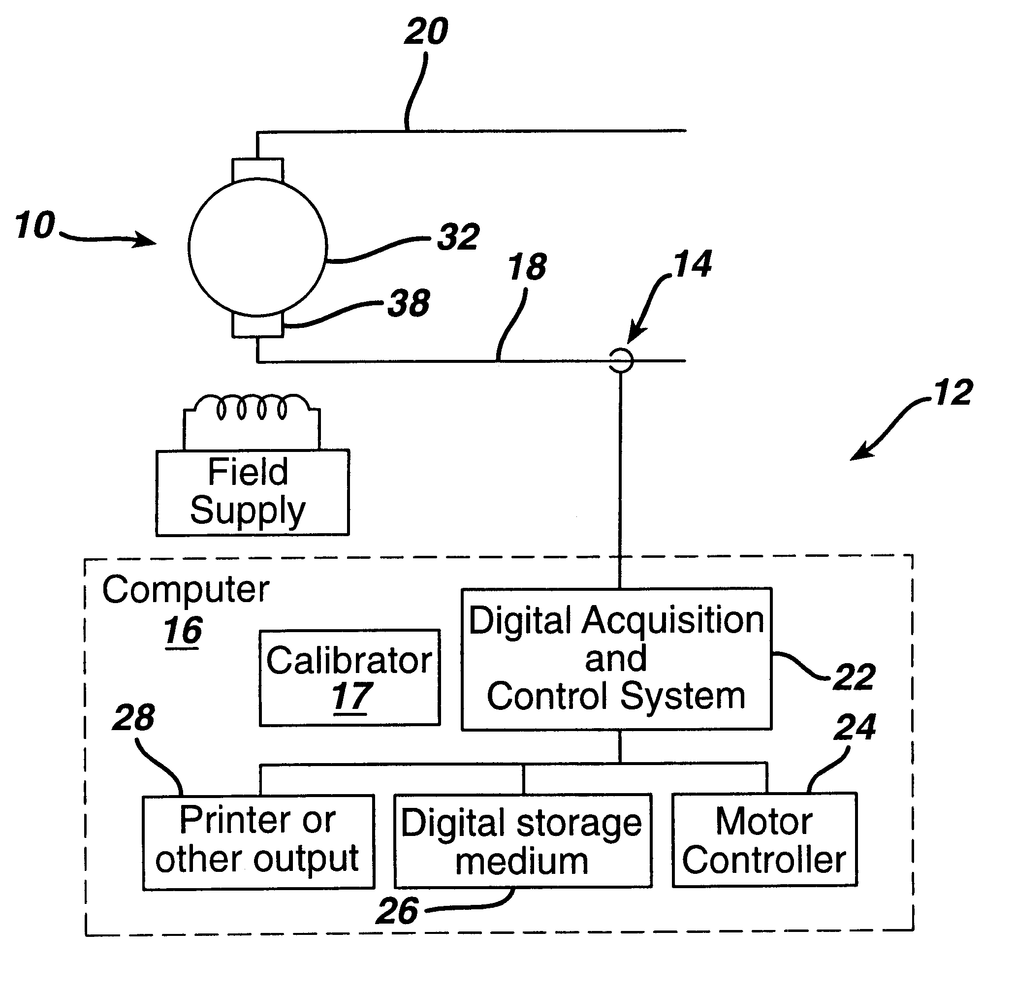
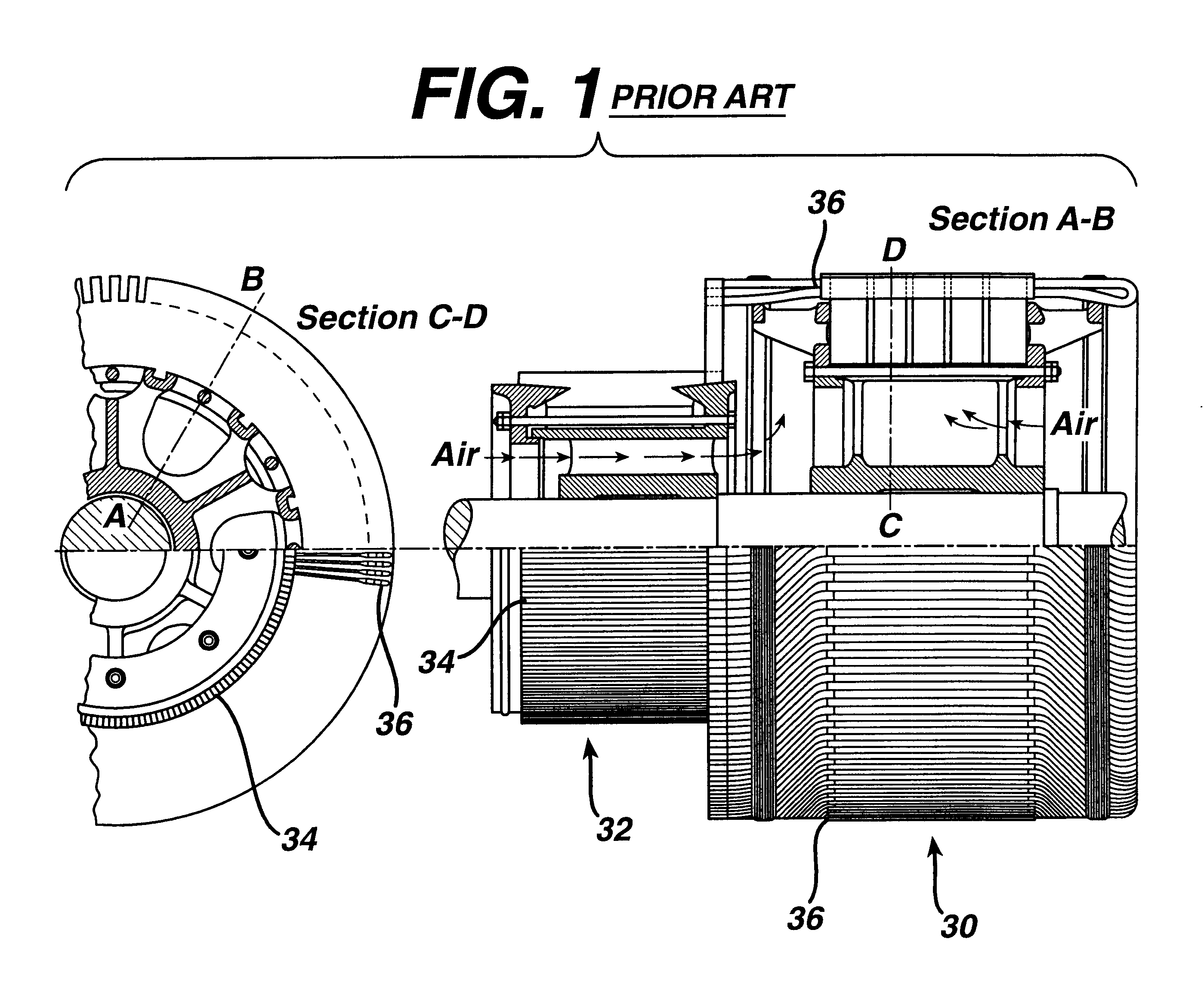
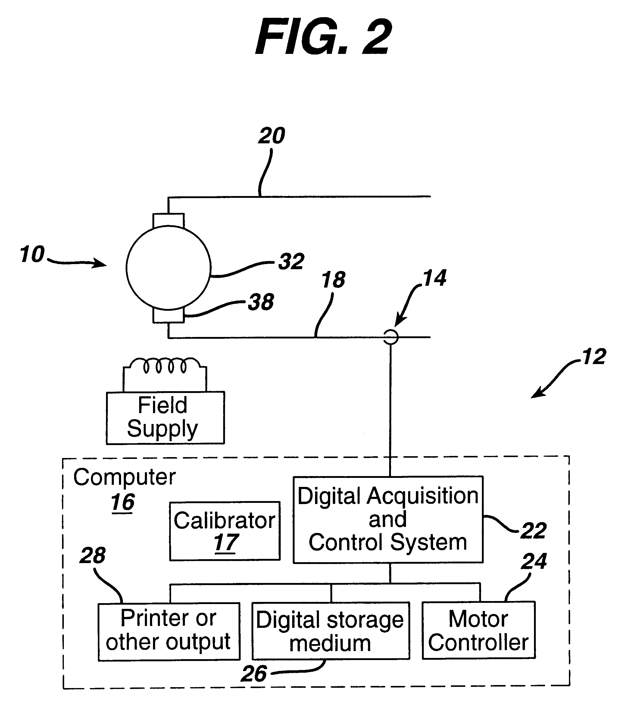
FIG. 1 includes partially cross-sectional axial and longitudinal views of a conventional dc machine commutator 32 and armature 30 such as is shown in Albert Still, ELEMENTS OF ELECTRICAL DESIGN, 2.sup.nd edition, 3.sup.rd impression, p 212 (1932), and FIG. 2 is a block diagram of a monitoring system for a direct current machine which can be used in accordance with several embodiments of the present invention.

In accordance with one embodiment of the present invention, a direct current machine 10 monitoring system 12 includes: (a) a current sensor 14 for monitoring load current of the machine; and (b) a computer 16 for (i) obtaining a rotation frequency of the machine by (aa) obtaining a first power spectrum of the load current, (bb) identifying significant peaks of the power spectrum, (cc) identifying one of the significant peaks as indicative of rotation frequency, and (dd) identifying a frequency of the identified peak as the rotation frequency, (ii) multiplying the rotation freque...


PUM


Abstract

A direct current machine monitoring system includes a current sensor for monitoring load current of the machine; and a computer for obtaining a power spectrum in a range including a machine trait-passing frequency, determining a magnitude of a maximum peak in the power spectrum in a range including the trait-passing frequency plus or minus an uncertainty frequency, and evaluating the magnitude of the maximum peak to assess a condition of the machine. The computer may additionally or alternatively be used for obtaining a low frequency power spectrum of the load current, obtaining at least one magnitude of a component of the power spectrum at a respective predicted frequency, and evaluating the at least one magnitude of the component to assess the condition of the machine.

Description

The invention relates generally to direct current machines and more particularly to direct current machine monitoring systems.A degraded commutator of a direct current (dc) machine will show excessive sparking as brushes bounce over the rough surface and the conduction period for a particular segment ends prematurely or as a winding remains shorted for too long by a spark region which extends between segments. Ultimately a short circuit will develop, through an extended spark region over the commutator bars, between opposite-polarity brushes. This "flashover" is often severe enough to destroy the machine. Sparking can additionally be caused by factors such as worn down brushes, improper brush positioning, or load or supply problems, for example.On-line monitoring of commutation quality degradation as a measure of brush and / or commutator degradation or wear, for example, or as a precursor to flashover in dc machines can provide a significant advantage in steel mill, paper mill, and l...

Claims


Application Information

Patent Timeline
IPC IPC(8): G01R31/34
CPCG01R31/343
Inventor KLIMAN, GERALD BURTBARTON, RICHARD KENNETHHOKANSON, PAUL ROBERTTREANOR, MICHAEL PAULKOEGL, RUDOLPH ALFRED ALBERT
Owner GE GLOBAL SOURCING LLC
Features
  • Generate Ideas
  • Intellectual Property
  • Life Sciences
  • Materials
  • Tech Scout
  • Unparalleled Data Quality
  • Higher Quality Content
  • 60% Fewer Hallucinations
Learn More