Continuous carpet cleaning system

a carpet cleaning and continuous technology, applied in the field of waste liquid disposal systems, can solve the problems of inability to operate, inability to re-use, and inability to remove dirt from carpets,

Inactive Publication Date: 2003-02-04
NASETH JR DONALD
View PDF14 Cites 11 Cited by
  • Summary
  • Abstract
  • Description
  • Claims
  • Application Information

AI Technical Summary

Benefits of technology

In the preferred embodiment, the air control valve is an electric solenoid valve connected to a control means to prevent overfilling of the secondary recovery tank. In the preferred embodiment, the control means is a timer designed to continuously open and close the solenoid valve at regular, pre-selected intervals. In a second embodiment, the timer is replaced with float switches located inside the secondary recovery tanks that automatically control the ports on the air control valves when the waste water reaches a specific level inside the secondary recovery tank. An optional control means is also provided inside the primary recovery tank to prevent overfilling of the primary recovery tank when the first check valve closes.

Problems solved by technology

The dirty water removed from the carpet contains harmful chemicals and cannot be deposited in storm drains.
One problem with using sensing switches located inside the holding tank is that they often fail to operate when clogged or corroded.
Another problem is that when the waste water is discarded from the holding tank, the vacuum pressure is temporarily lost thereby discontinuing removal of waste water from the carpet.

Method used


Image

  • Continuous carpet cleaning system
  • Continuous carpet cleaning system
  • Continuous carpet cleaning system

Examples


Embodiment Construction

)

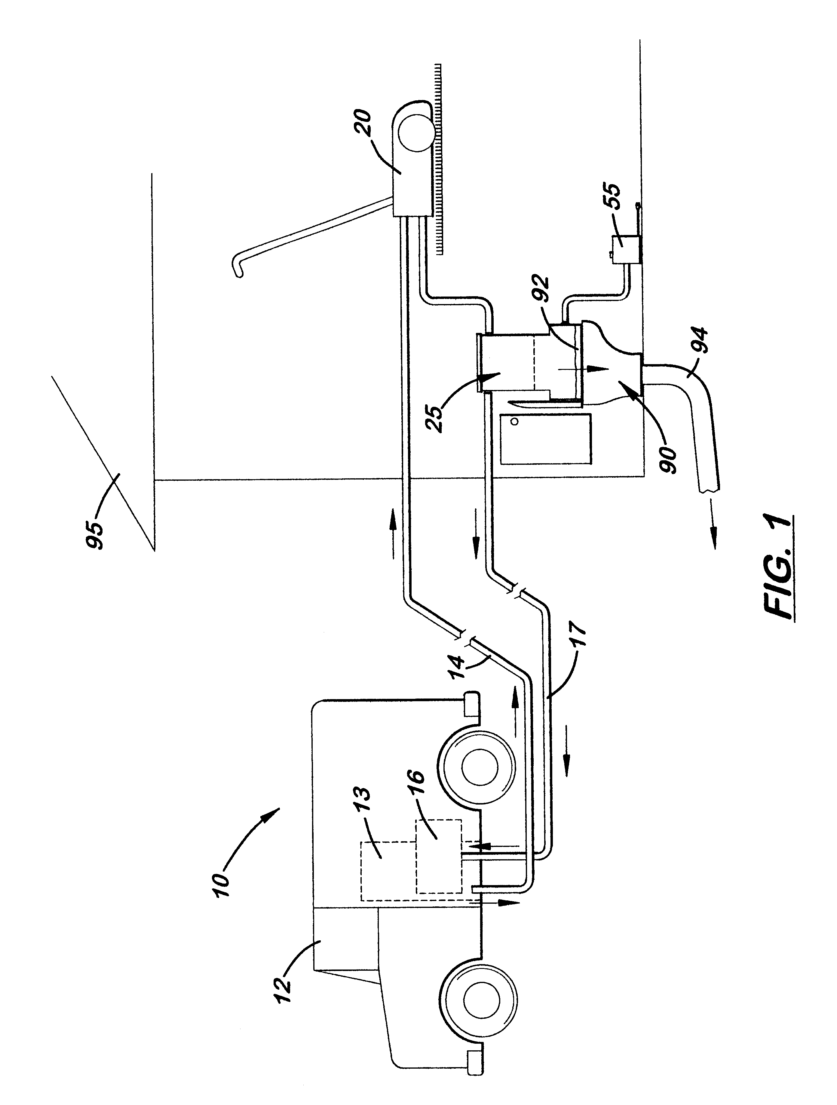
Referring to the FIG. 1, there is shown and described a carpet cleaning system, generally referenced as 10, that first delivers cleaning water from a water tank 13 located in a truck 12 via a water line 14 connected to a carpet cleaning apparatus 20 located in a home or business 95. Using vacuum pressure created by a vacuum source 16 located in the truck 12, waste water 92 from the carpet is removed by the cleaning apparatus 20 and delivered to an improved waste disposal tank 25 designed to continuously receive the waste water 92 and automatically discard it into a toilet 90 or a sewer line 94.

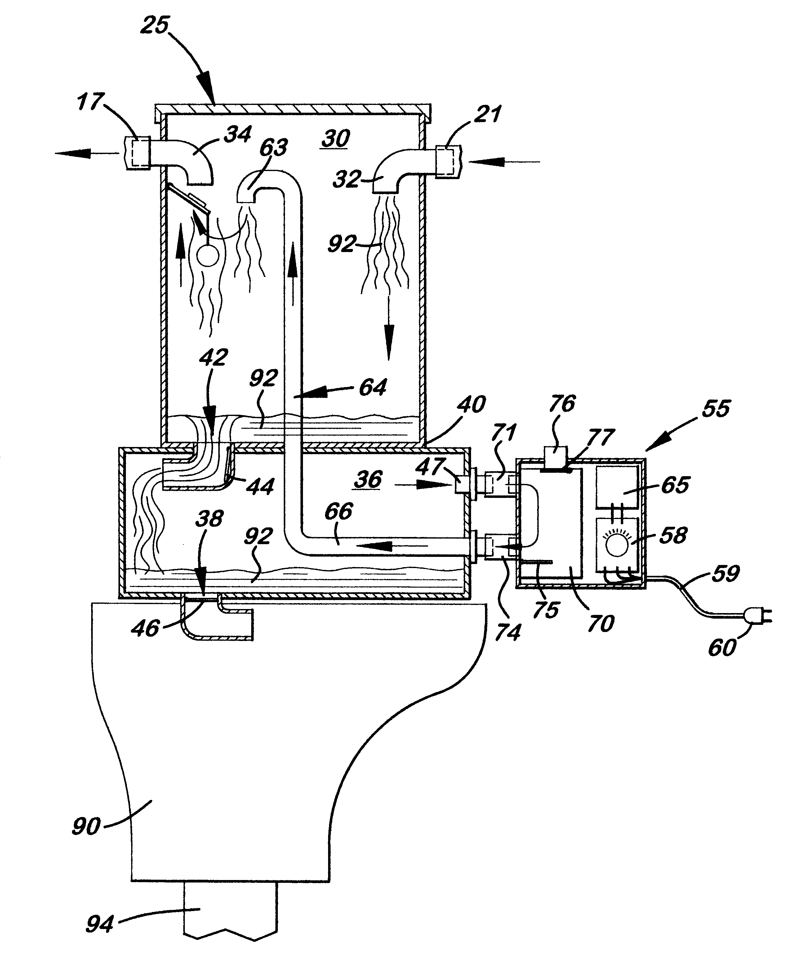
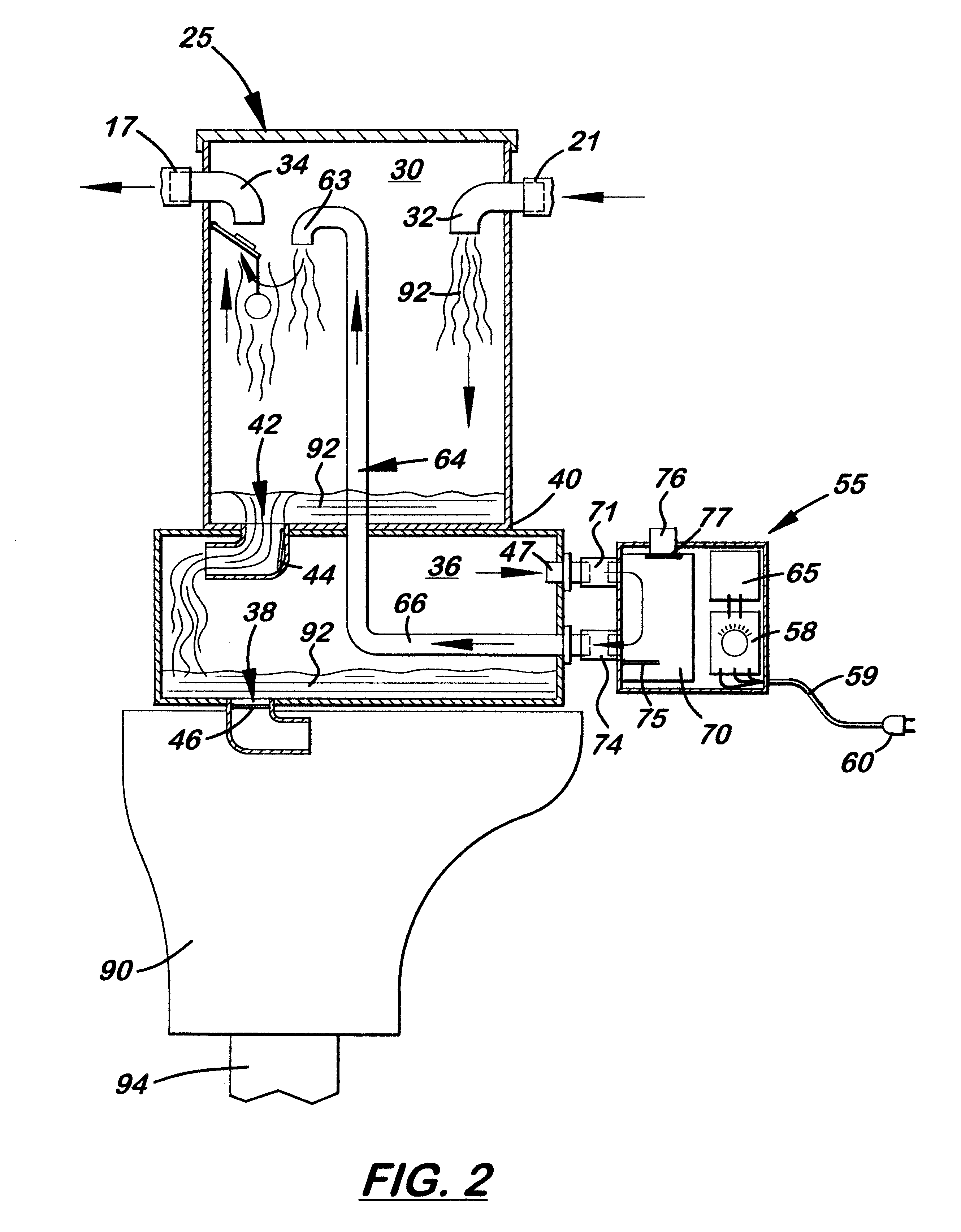
As shown in FIGS. 2-4, the disposal tank 25 is a closed structure which is divided into an upper primary recovery tank 30 and a lower secondary recovery tank 36. The primary recovery tank 30 includes a waste water inlet port 32 that connects to a second vacuum hose 21 connected at one end to the carpet cleaning apparatus 20. Also formed on the primary recovery tank 30 is an exhaust air outlet...


PUM


Abstract

A carpet cleaning system that delivers heated cleaning water from a truck to a carpet cleaning apparatus and an improved waste disposal tank designed to receive the waste water and deposit it into the toilet or sewer drain when the disposal tank is full. The disposal tank is divided into an upper primary recovery tank and a lower recovery tank. A main vacuum line and waste water return line are connected to the primary recovery tank. Disposed between the primary and secondary recovery tanks is a first check valve that controls the flow of waste water therebetween. Connected over the outlet port on the secondary recovery tank is a second check valve that operates in opposite direction to the first check valve. Attached to the secondary recovery tank is an air control valve that controls the flow of air from the primary recovery tank or the outside air into the secondary recovery tank. A timer or a float valve is connected to the air control valve to selectively control its operation. When the air control valve is inactivated, the air pressures in the tanks are equal and sub-atmospheric. When the air control valve is activated, the flow of air between the tanks is discontinued and outside air is able to flow into the secondary recovery tank. When outside air enters the secondary recovery tank, the first check valve closes to maintain vacuum pressure inside the primary recovery tank for cleaning, and the second check valve opens to allow discharge of the waste water from the secondary recovery tank.

Description

1. Field of the InventionThis invention pertains to a waste liquid disposal system and, more particularly, to such a system for cleaning carpets.2. Description of the Related ArtCarpet cleaners that spray a detergent solution into a rug and then vacuum the dirty water out of the rug are widely used by small businesses and homeowners. The dirty water removed from the carpet contains harmful chemicals and cannot be deposited in storm drains. Instead, this dirty water must be deposited in sewer lines that eventually lead to a sewer treatment plant. Because many homes and businesses are connected to sewer lines, users often deposit the waste water directly in their toilets.Most mug cleaners include a holding tank in which the waste water is temporarily deposited. Some cleaners, such as the one disclosed in U.S. Pat. No. 4,823,428, include sensing switches located inside the holding tank that detect when the waste water inside the holding tank is at a specific level. When the waste water...

Claims


Application Information

Patent Timeline
Patent Type & Authority Patents(United States)
IPC IPC(8): A47L5/38A47L5/22
CPCA47L5/38Y10T137/3109Y10T137/3124
Inventor NASETH, SR., DONALD P.
Owner NASETH JR DONALD
Why Eureka
Try Eureka