
Positioning system and method for orienting an ablation element within a pulmonary vein ostium

a technology of pulmonary vein ostium and positioning system, which is applied in the field of tissue ablation device assembly, can solve the problems of proarrhythmia and long-term ineffectiveness, surgical "maze" procedure may be substantially efficacious, and not generally believed to be entirely effective, so as to prevent atrial arrhythmia, eliminate arrhythmogenic conduction, and high-intensity methods

Inactive Publication Date: 2003-02-04
ATRIONIX
View PDF190 Cites 1135 Cited by
  • Summary
  • Abstract
  • Description
  • Claims
  • Application Information

AI Technical Summary

Benefits of technology

The "maze procedure" as performed in the left atrium generally includes forming vertical incisions from the two superior pulmonary veins and terminating in the region of the mitral valve annulus, traversing the region of the inferior pulmonary veins en route. An additional horizontal line also connects the superior ends of the two vertical incisions. Thus, the atrial wall region bordered by the pulmonary vein ostia is isolated from the other atrial tissue. In this process, the mechanical sectioning of atrial tissue eliminates the arrhythmogenic conduction from the boxed region of the pulmonary veins to the rest of the atrium by creating conduction blocks within the aberrant electrical conduction pathways. Other variations or modifications of this specific pattern just described have also been disclosed, all sharing the primary purpose of isolating known or suspected regions of arrhythmogenic origin or propagation along the atrial wall.
While the "maze" procedure and its variations as reported by Dr. Cox and others have met some success in treating patients with atrial arrhythmia, its highly invasive methodology is believed to be prohibitive in most cases. However, these procedures have provided a guiding principle that electrically isolating faulty cardiac tissue may successfully prevent atrial arrhythmia, and particularly atrial fibrillation caused by arrhythmogenic conduction arising from the region of the pulmonary veins.
Furthermore, the specific desired location for the ablation member that is adapted to ablatively couple the ablation element to the desired circumferential region of tissue may not be predetermined or known for a particular patient prior to positioning the ablation member according to the embodiments herein described. The system and method of the present invention therefore allows the respective anatomy of a given patient to be self defining of such desired location. The position monitoring assembly senses when the ablation member's position is at a location that enables ablative coupling of the ablation element to a circumferential region of tissue such that the desired circumferential conduction block may be achieved.
FIG. 16K shows a segmented view of a left atrium and pulmonary veins with a similar circumferential lesion as that shown in FIG. 16F, although further showing the circumferential lesion in combination with other lesions formed along the posterior left atrial wall in a patient in order to form one type of lesion pattern for preventing atrial arrhythmia.

Problems solved by technology

Such pharmacological solutions, however, are not generally believed to be entirely effective in many cases, and are even believed in some cases to result in proarrhythmia and long term inefficacy.
However, more recent reports predict that the surgical "maze" procedure may be substantially efficacious when performed only in the left atrium.
Cox and others have met some success in treating patients with atrial arrhythmia, its highly invasive methodology is believed to be prohibitive in most cases.
A difficulties arises, however, with positioning and regulating the ablation process with one or more thermocouples where ablation occurs though an inflatable balloon, such as when the device assembly disclosed in PCT Patent Application Publication No.
Thermocouples are usually mounted to the catheter shaft, and if ablation occurs at an interface between the balloon and the tissue, the thermocouples do not accurately measure the temperature because of their remote distance relative to the ablation site.
Furthermore, the specific desired location for the ablation member that is adapted to ablatively couple the ablation element to the desired circumferential region of tissue may not be predetermined or known for a particular patient prior to positioning the ablation member according to the embodiments herein described.

Method used


Image

  • Positioning system and method for orienting an ablation element within a pulmonary vein ostium
  • Positioning system and method for orienting an ablation element within a pulmonary vein ostium
  • Positioning system and method for orienting an ablation element within a pulmonary vein ostium

Examples


Embodiment Construction

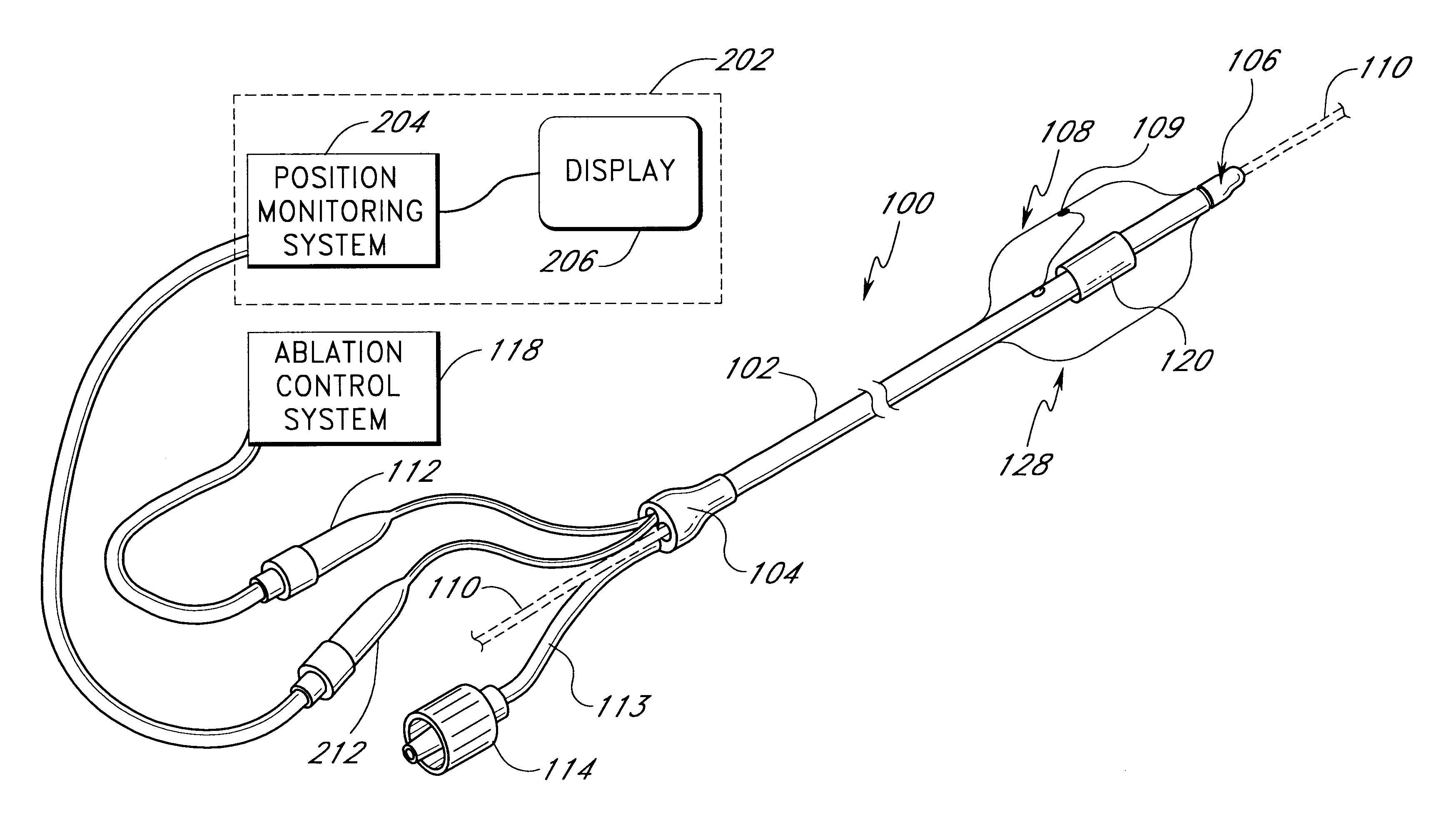
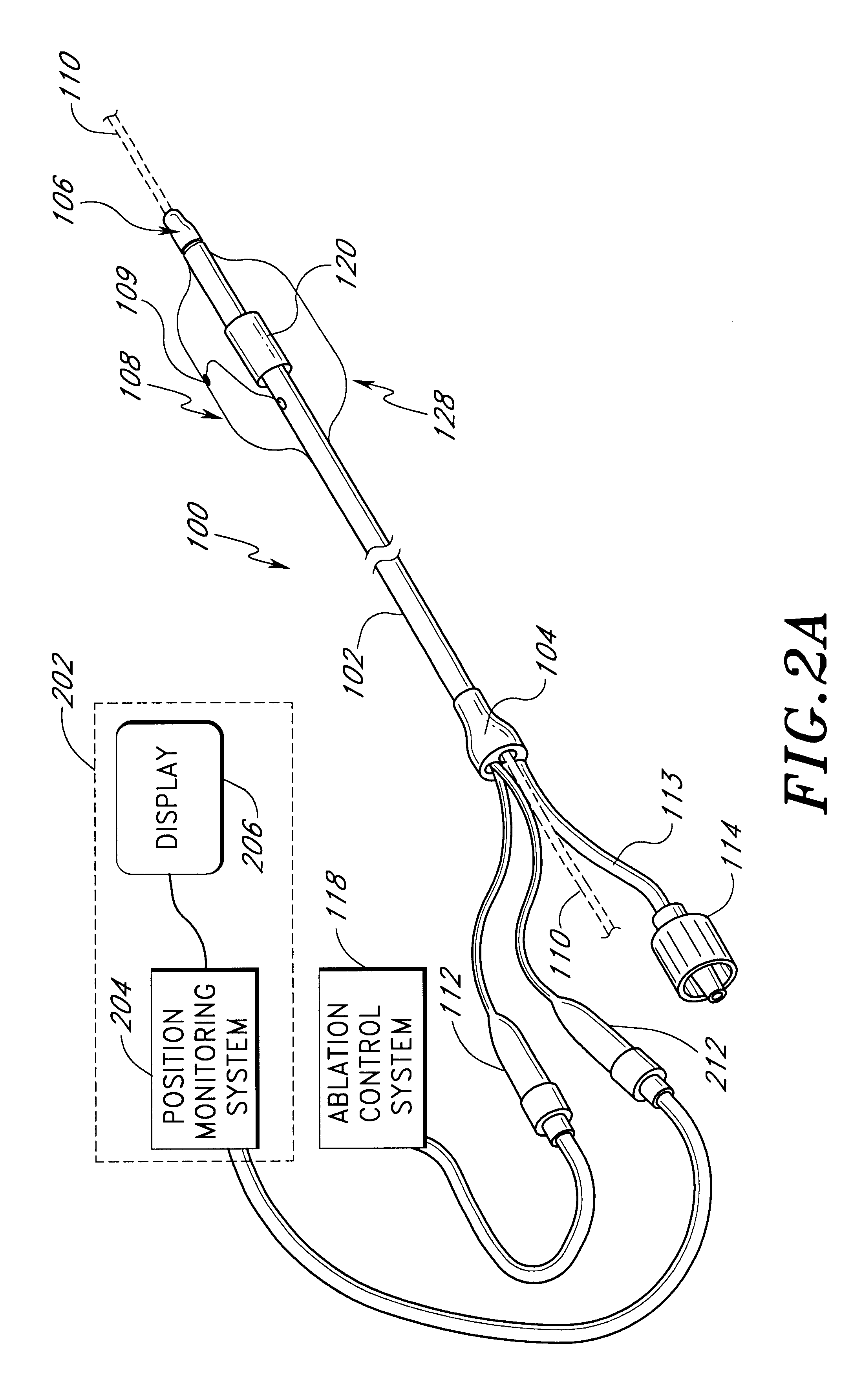
The following describes several ablation devices of a medical device system. Several of the disclosed devices employ sensors (e.g., thermocouples, electrodes, etc.) used with an expandable member of the medical article to sense a variety of parameters relating to the progression and efficacy of the ablation process, and illustrate a variety of ways in which such sensors can be used with the expandable member.

Several of the disclosed devices also include a position monitoring system that allows a clinician to precisely locate a distal end of the medical device within a body space by using feedback information provided by the system. Such feedback information is indicative of the position of the distal end of the medical device within the body space. The following devices of the position monitoring system are particularly well suited for applications involving positioning an ablation member at an area where a pulmonary vein extends from a left atrium and relative to a targeted circumf...


PUM


Abstract

This invention relates to a surgical device and method. More particularly, it relates to a tissue ablation device assembly and method using a circumferential ablation member in combination with a position monitoring assembly in order to position the circumferential ablation member along a circumferential region of tissue at a location where a pulmonary vein extends from a left atrium.

Description

1. Field of the InventionThe field of the invention relates to a surgical device and method. More particularly, it relates to a tissue ablation device assembly and method using a circumferential ablation member in combination with a position monitoring assembly in order to position the circumferential ablation member along a circumferential region of tissue at a location where a pulmonary vein extends from a left atrium.2. Description of Related ArtMany local energy delivery devices and methods have been developed for treating the various abnormal tissue conditions in the body, and particularly for treating abnormal tissue along body space walls which define various body spaces in the body. For example, various devices have been disclosed with the primary purpose of treating or recanalizing atherosclerotic vessels with localized energy delivery. Several prior devices and methods combine energy delivery assemblies in combination with cardiovascular stent devices in order to locally d...

Claims


Application Information

Patent Timeline
IPC IPC(8): A61B18/00A61B18/14A61N7/02A61N7/00A61B17/00
CPCA61B18/00A61B18/1492A61N7/02A61B2017/00106A61B2018/00214A61B2018/00261A61B2017/00243
Inventor MAGUIRE, MARK A.O'SULLIVAN, MARTIN F.CARCAMO, EDWARD L.LESH, MICHAEL D.SCHAER, ALAN K.TAYLOR, KEVIN J.PICAZO, GUILLERMO P.
Owner ATRIONIX
Learn More