Embolic coil hydraulic deployment system with purge mechanism
- Summary
- Abstract
- Description
- Claims
- Application Information
AI Technical Summary
Problems solved by technology
Method used
Image
Examples
Embodiment Construction
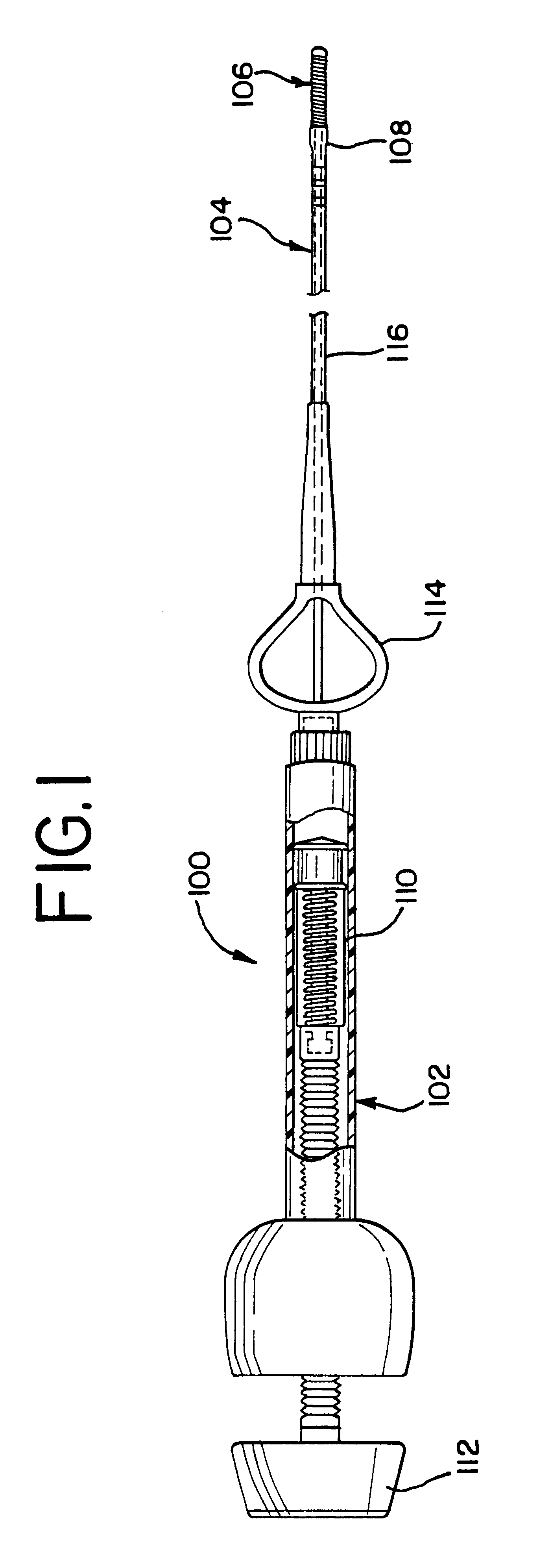
FIG. 1 generally illustrates the vascular occlusive coil deployment system 100 which is comprised of a hydraulic injector or syringe 102, coupled to the proximal end of a catheter 104. An embolic coil 106 includes a proximal headpiece 122 which is disposed within the lumen of the distal end 108 of the catheter. The headpiece 122 is tightly held within the lumen of the distal section 108 of the catheter 104 until the deployment system is activated for release of the coil. As may be seen, the syringe 102 includes a threaded piston 110 which is controlled by a handle 112 for infusing fluid into the interior of the catheter 104. Also as illustrated, the catheter 104 includes a winged hub 114 which aides in the insertion of the catheter into the vascular system of the body.
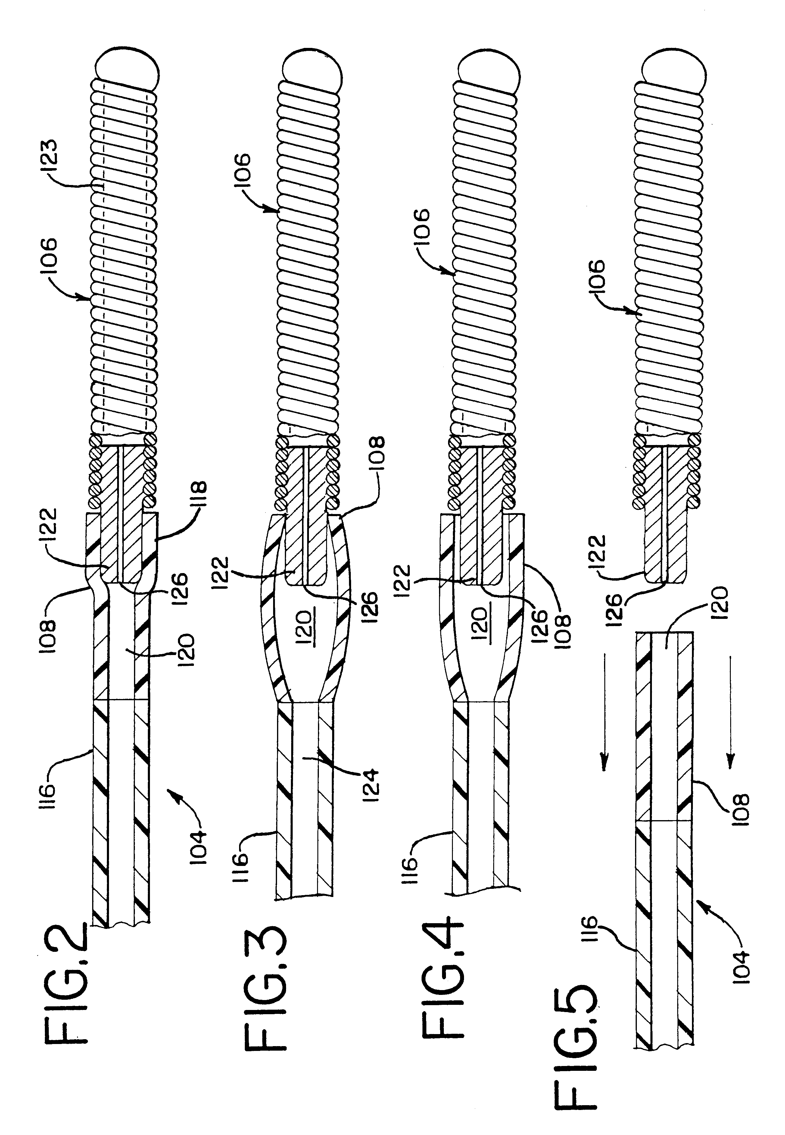
FIG. 2 illustrates in more detail the distal end of the catheter 104. The catheter 104 includes a proximal section 116 and the distal section 108. The embolic coil 106 is tightly wrapped and bonded to the distal portio...
PUM
 Abstract
Description
Claims
Application Information
 - R&D
- Intellectual Property
- Life Sciences
- Materials
- Tech Scout
- Unparalleled Data Quality
- Higher Quality Content
- 60% Fewer Hallucinations
Browse by: Latest US Patents, China's latest patents, Technical Efficacy Thesaurus, Application Domain, Technology Topic, Popular Technical Reports.
© 2025 PatSnap. All rights reserved.Legal|Privacy policy|Modern Slavery Act Transparency Statement|Sitemap|About US| Contact US: help@patsnap.com


