

Navigable telepresence method and system utilizing an array of cameras
a telepresence system and camera array technology, applied in the field of telepresence systems, can solve problems such as the inability of potential visitors to a museum to view an exhibit, the inability of music concert producers to turn back fans, and the limited viewing of such venues
Inactive Publication Date: 2003-02-18
KEWAZINGA CORP
View PDF46 Cites 83 Cited by
- Summary
- Abstract
- Description
- Claims
- Application Information
AI Technical Summary
Problems solved by technology
The viewing of such venues is limited by time, geographical location, and the viewer capacity of the venue.
For example, potential visitors to a museum may be prevented from viewing an exhibit due to the limited hours the museum is open.
Similarly, music concert producers must turn back fans due to the limited seating of an arena.
In short, limited access to venues reduces the revenue generated.
While such broadcasting increases access to the venues, it involves considerable production effort.
These editorial and production efforts are costly.
In some instances, the broadcast resulting from these editorial and production efforts provides viewers with limited enjoyment.
Thus, the broadcast contains limited viewing angles and perspectives of the venue.
Moreover, the viewing angles and perspectives presented in the broadcast are those selected by a producer or director during the editorial and production process; there is no viewer autonomy.
Furthermore, although the broadcast is often recorded for multiple viewings, the broadcast has limited content life because each viewing is identical to the first.
A viewer fortunate enough to attend a venue in person will encounter many of the same problems.
Even if a viewer were allowed free access to the entire arena to videotape the venue, such a recording would also have limited content life because each viewing would be the same as the first.
In this regard, operation of the system is complicated.
Furthermore, because the camera views are contiguous, typically at right angles, changing camera views results in a discontinuous image.
Such 360 degree camera systems also suffer from drawbacks.
In particular, such systems limit the user's view to 360 degrees from a given point perspective.
Also, with regard to the system of U.S. Pat. No. 5,187,571, in order to achieve the contiguity between camera views, a relatively complex arrangement of mirrors is required.
Method used
View moreImage
Smart ImageViewing Examples

Examples
embodiments covered
Although the present invention has been described in terms of certain preferred embodiments, other embodiments that are apparent to those of ordinary skill in the art are also intended to be within the scope of this invention. Accordingly, the scope of the present invention is intended to be limited only by the claims appended hereto.
Login to View More PUM
 Abstract
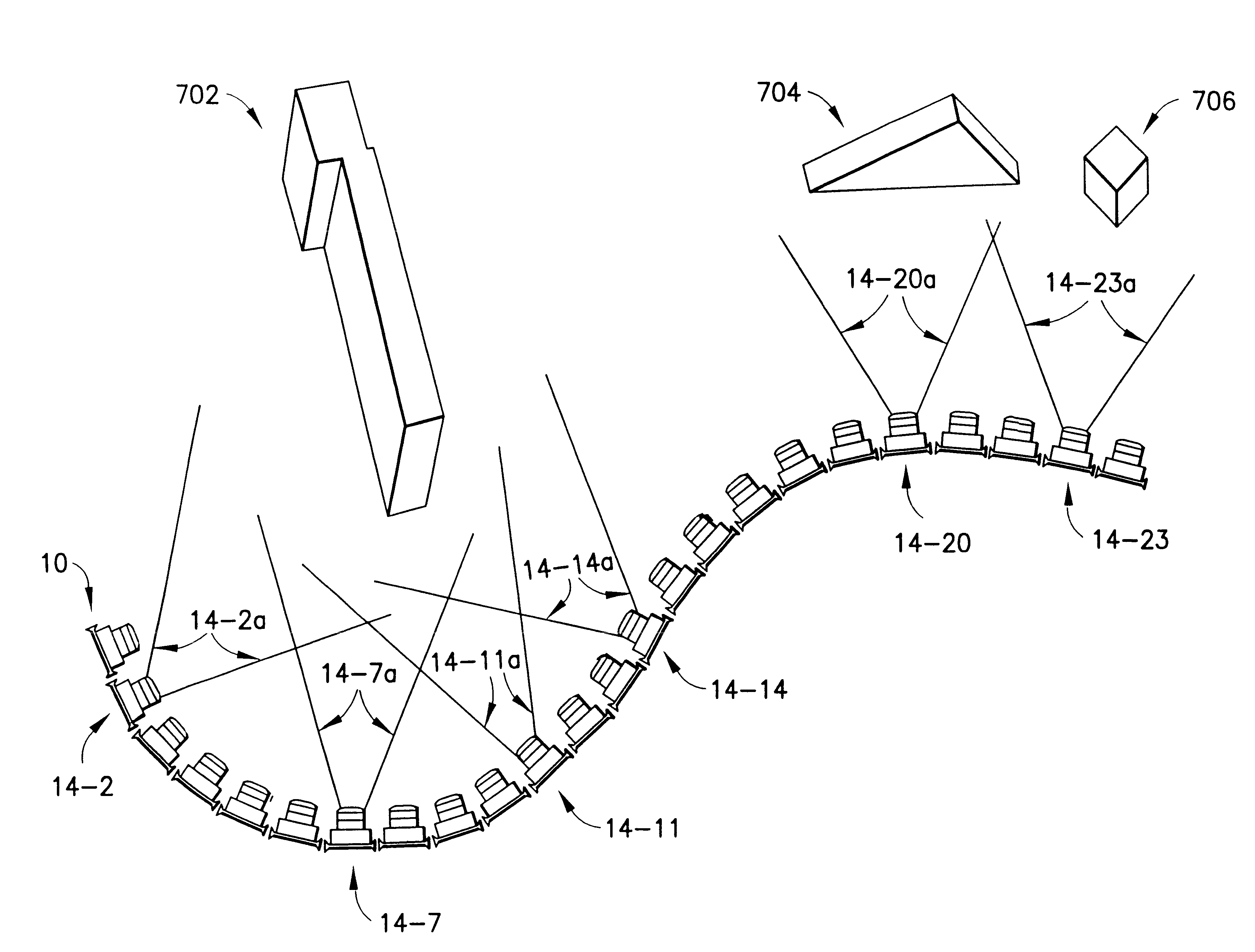
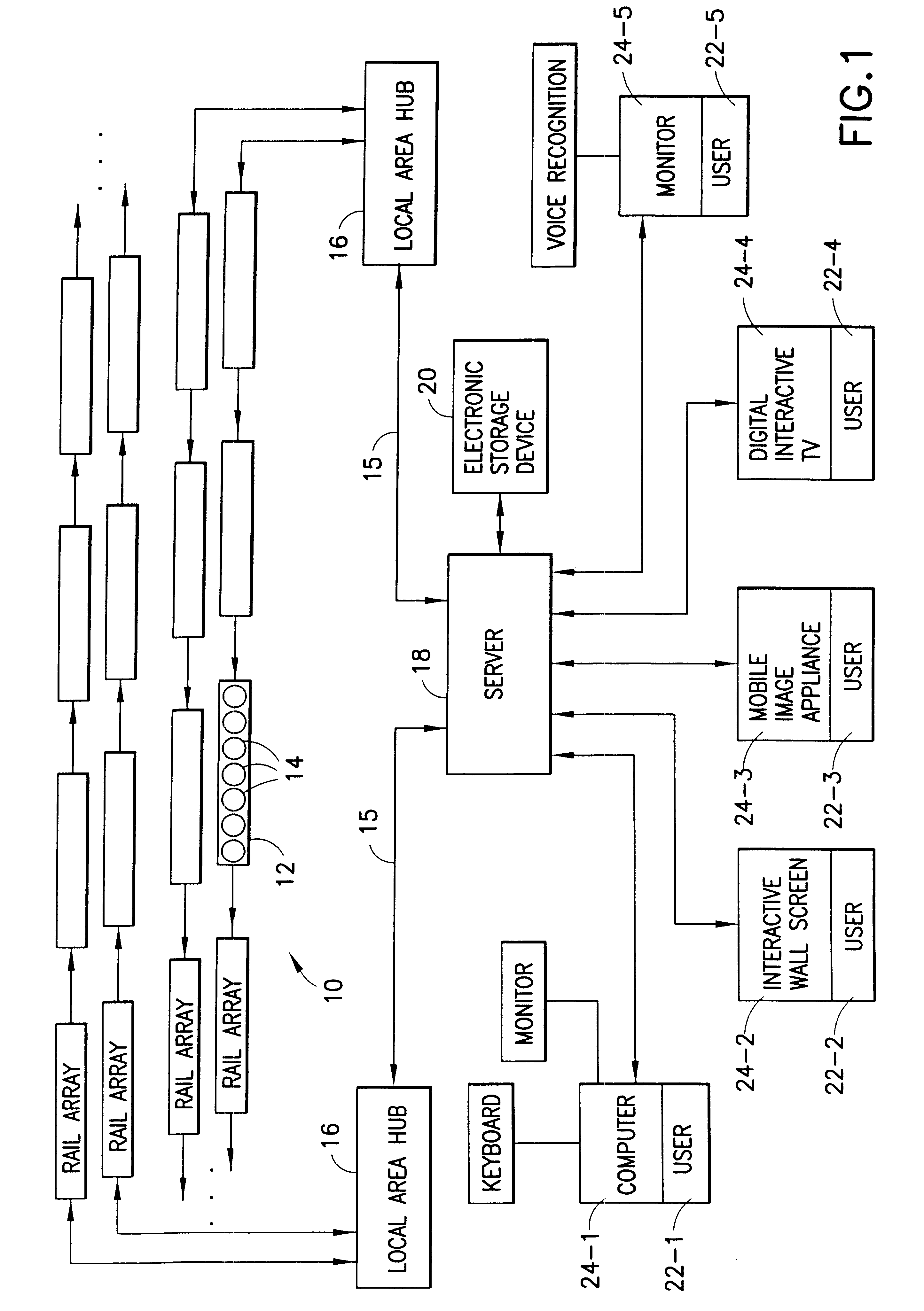
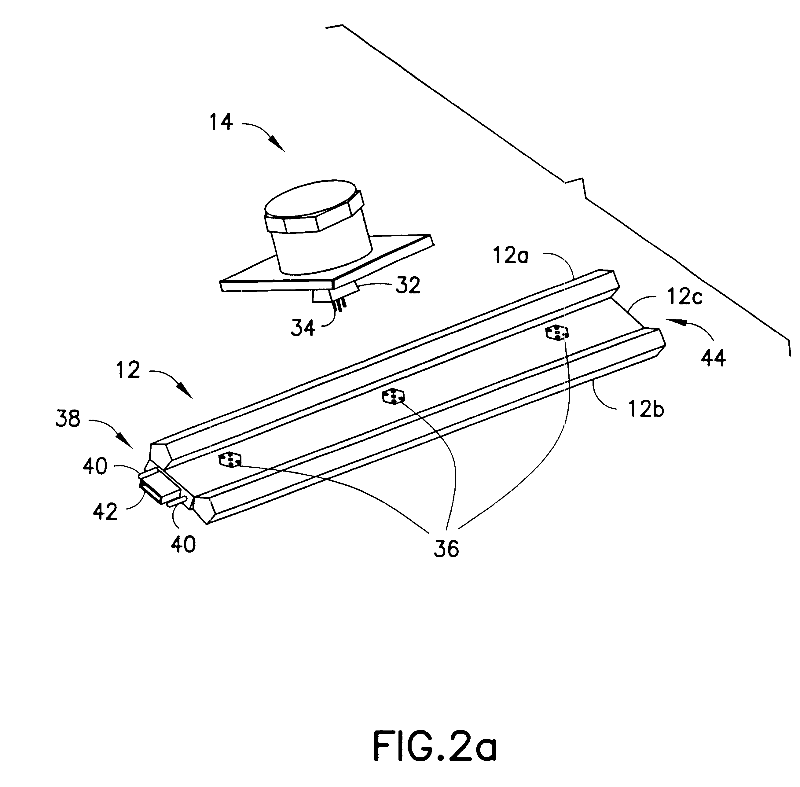
A telepresence system for providing a first user with a first display of an environment and simultaneously and independently providing a second user with a second display of the environment. In certain embodiments, the system includes a plurality of arrays of cameras, with each arrays are situated at varying lengths from the environment. In one embodiment, the cameras situated around the environment are removed after the cameras in the array are have transmitted the camera output to an associated storage node. A first user interface device has first user inputs associated with movement along a first path in the array, and a second user interface device has second user inputs associated with movement along a second path. The system interprets the first inputs and selects outputs from the storage nodes in the first path, and interprets second inputs and selects outputs from the storage nodes in the second path independently of the first inputs, thereby allowing a first user and a second user to navigate simultaneously and independently through the environment. In another embodiment, a telepresence system includes various techniques for mixing images of cameras along each path, such as, mosaicing and tweening, for effectuating seamless motion along such paths.
Description
1. Field Of The InventionThe present invention relates to a telepresence system and, more particularly, to a navigable camera array telepresence system and method of using same.2. Description Of Related ArtIn general, a need exists for the development of telepresence systems suitable for use with static venues, such as museums, and dynamic venues or events, such as a music concerts. The viewing of such venues is limited by time, geographical location, and the viewer capacity of the venue. For example, potential visitors to a museum may be prevented from viewing an exhibit due to the limited hours the museum is open. Similarly, music concert producers must turn back fans due to the limited seating of an arena. In short, limited access to venues reduces the revenue generated.In an attempt to increase the revenue stream from both static and dynamic venues, such venues have been recorded for broadcast or distribution. In some instances, dynamic venues are also broadcast live. While such...
Claims
Login to View More Application Information
Patent Timeline
 Patent Type & AuthorityPatents(United States)
IPC IPC(8): H04N7/18H04N5/225G03B37/04H04N13/243
CPCG03B37/04H04N7/15H04N5/2627H04N7/181H04N7/185H04N13/0051H04N13/0055H04N13/0239H04N13/0242H04N13/0296G06F3/011H04N5/262H04N7/142G06F3/04815H04N5/2624H04N5/265H04N5/2259H04N13/0059H04N13/0246G06F3/0354H04N13/239H04N13/167H04N13/189H04N13/194H04N13/243H04N13/246H04N13/296H04N7/157H04N23/58H04N13/204
InventorSOROKIN, SCOTTWORLEY, DAVID C.WEBER, ANDREW H.
OwnerKEWAZINGA CORP