
Cutting device for elongated materials

Inactive Publication Date: 2003-02-25
ORANGE COUNTY INDAL SEWING MACHINE
View PDF11 Cites 13 Cited by
  • Summary
  • Abstract
  • Description
  • Claims
  • Application Information

AI Technical Summary

Benefits of technology

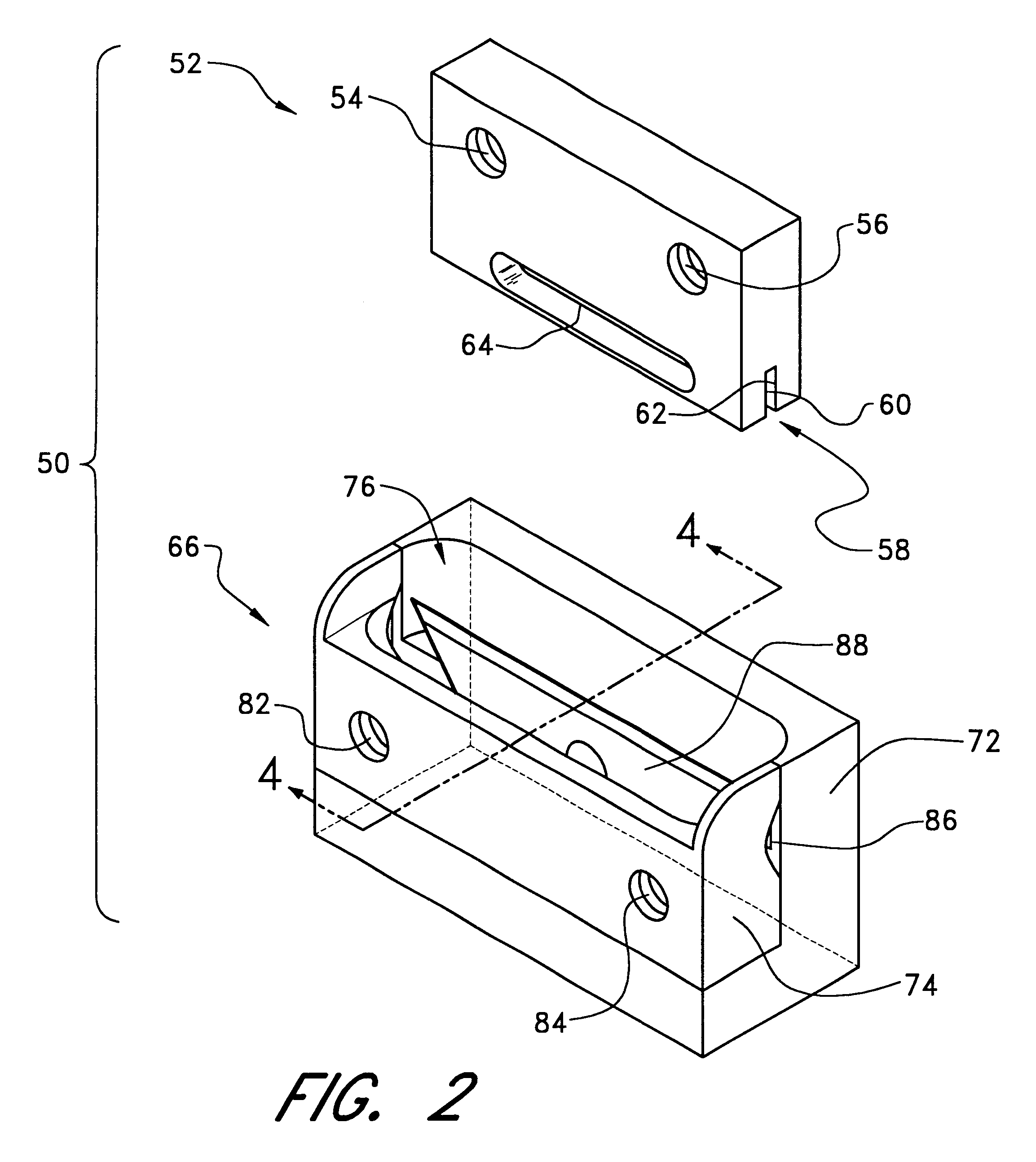
Another aspect of the invention involves a device that attaches to a sewing machine for cutting elongated materials, comprising a hydraulic drive attached to the sewing machine and moveable between a retracted position and an extended position; and a ram connected to the drive, the ram having a channel within at least a portion of the ram that extends along an outlet to assist in removing build-up of excess material that has been cut by the device; and a receptacle attached to the sewing machine, the receptacle having a hollow within at least a portion of the receptacle that accepts at least a portion of the ram when the ram is in the extended position and a blade recessed within the receptacle.
The cutting device of the present invention thus provides a fast and inexpensive way for separating a variety of elongated materials, in part because of the cutting blade. The device also provides accurate cutting of elongated materials by inhibiting movement of the material during the cutting sequence, in part because of the arrangement of the channel walls of the ram and the channel walls of the receptacle. The device further provides for operator safety by using an unexposed blade recessed within a relatively narrow hollow. The device is also long-lasting since the recessed blade less exposed and therefore a large number of cuts may be made before the blade dulls.

Problems solved by technology

However, this procedure takes a significant amount of time and is therefore disadvantageous in commercial clothing manufacturing operations.
However, automated scissors tend to be sensitive to wear, among other disadvantages, and also tend to be unsafe.
Although this configuration provides a device that can separate thread, it has significant drawbacks that include: creating a significant likelihood that an operator's finger may be accidentally caught within the device and cut, as well as causing slippage of the thread during the cutting sequence which results in an inaccurate lengthwise cut.
If these extraneous materials are not removed from the channel 58, they tend to build up and wedge the channel 58 apart, which is disadvantageous to prolonged use of the device 50.

Method used


Image

  • Cutting device for elongated materials
  • Cutting device for elongated materials
  • Cutting device for elongated materials

Examples


Embodiment Construction

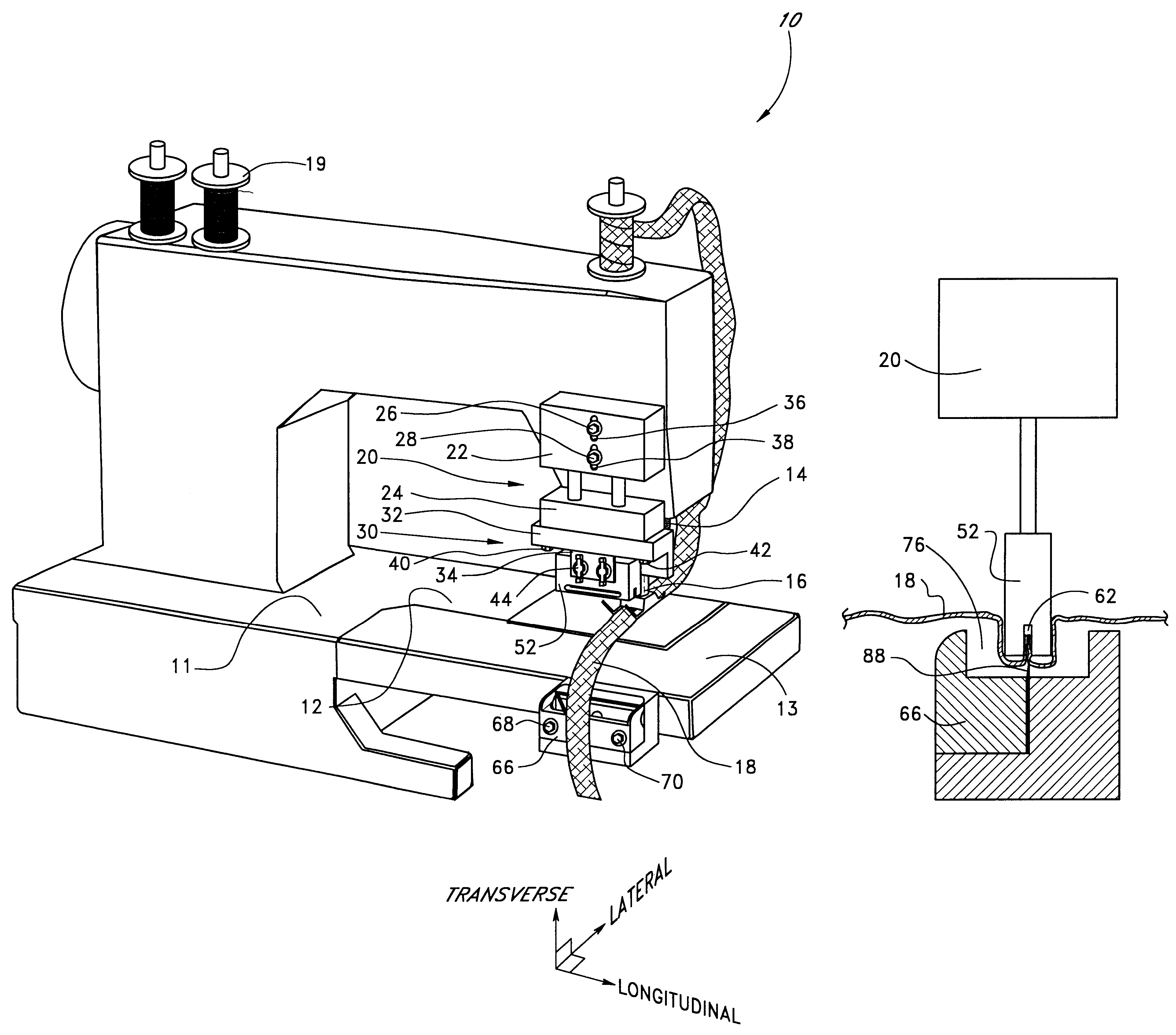
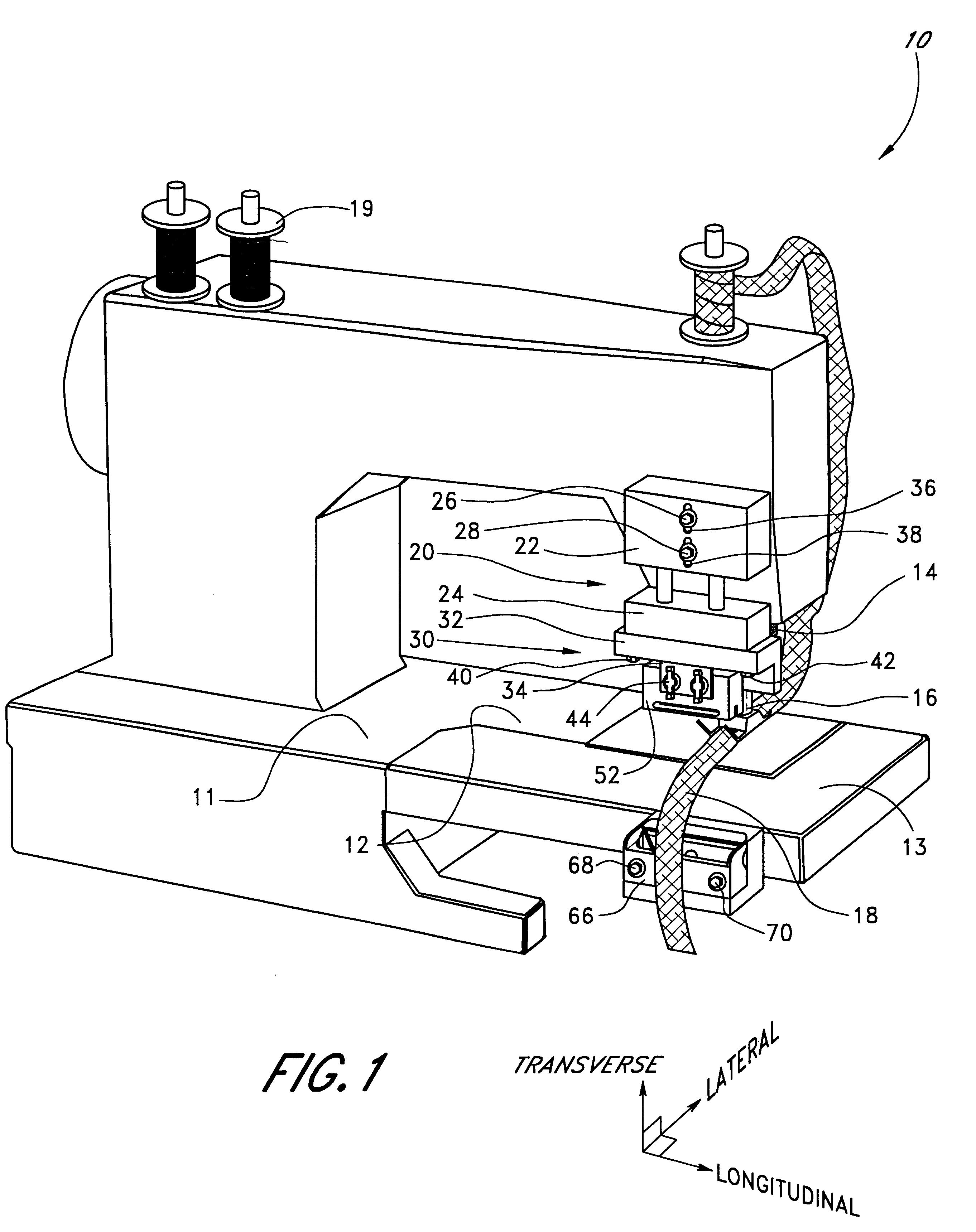
A cutting device 50a in accordance with another preferred embodiment of the invention is illustrated in FIGS. 1-7. The chief differences between this embodiment and the previous embodiment is the receptacle configuration 66a, the manner in which the receptacle 66a is attached to the sewing machine 10a, the transverse depth of the channel 52 and the cutting operation. Accordingly, the above description applies equally to the embodiment of FIGS. 8-12, unless otherwise indicated. In addition, like reference numerals are used to indicate like features to the two embodiments, with the letter designation "a" added as a suffix to refer to particular features of the present embodiment.

The concepts used in the cutting device 50a described herein are similar to the concepts of the previous embodiment. However, the particular structure and arrangement thereof used to accomplish these principles differs, as described below. Like the previous embodiment, the cutting device 50a comprises a first ...


PUM


Abstract

The cutting device comprises a first block or ram, and a second block or receptacle. The ram has a channel that extends along its longitudinal length, the channel is sized and configured to accept at least a portion of a cutting blade. The receptacle has a hollow sized and configured to accept at least a portion of the ram. The blade is arranged within the hollow and extends from the receptacle into the hollow and toward the ram. The blade is advantageously recessed within the ram. In one embodiment, the ram is attached to a drive coupled to a sewing machine, and the receptacle is attached to the sewing machine. The ram is moveable between a retracted position, in which the ram is separated from the receptacle, and an extended position, in which at least a portion of the ram is housed within the receptacle. By this configuration, elongated material may be placed between the receptacle and ram and then the ram can move from the retracted position to the extended position, whereby a portion of the elongated material is cut by the blade.

Description

1. Field of the InventionThe present invention relates in general to a cutting device for elongated materials and, more particularly, to a portable cutting device that attaches to a sewing machine for cutting thread, shoulder tape and the like.2. Description of the Related ArtMaterials used in the manufacture of clothing, such as cotton, polyester and rayon are typically coupled by thread to form a seam. Thread is also used for other purposes such as decoration, labeling and the like. In some textile applications, such as the manufacture of shirts, pants and jackets, shoulder tape extends along a seam to provide reinforcement, flexibility and / or discreteness to the seam. Shoulder tape may be adhesive or nonadhesive and has a typical width of about 5-15 mm and thickness of about 1-3 mm.Thread and shoulder tape are typically provided in spools of about 25-1,000 yards. Because only a portion of the thread or shoulder tape stored on the spool is required for a particular use, the materi...

Claims


Application Information

Patent Timeline
IPC IPC(8): D05B37/00D05B37/04D06H7/02D06H7/00
CPCD06H7/02D05B37/04
Inventor LEE, JOHN Y.
Owner ORANGE COUNTY INDAL SEWING MACHINE
Learn More