Applicator mitt assembly system

a technology of assembly system and mitt, which is applied in the field of application mitt assembly system, can solve the problems of mitt appearance unsightly and scratchy to the user's body, and achieve the effects of reducing material wastage, reducing material overhang, and eliminating or limiting the potential for the formation of overhanging material

Active Publication Date: 2019-02-12
SYNLATEX
View PDF20 Cites 0 Cited by
  • Summary
  • Abstract
  • Description
  • Claims
  • Application Information

AI Technical Summary

Benefits of technology

[0009]The provision of a system for manufacturing applicator mitts on an industrial scale allows for the efficient creation of applicator mitts having a strong and secure seam which, in this case, may be a heat-welded join. One of the problems of welding fabric and foam materials to one another has been in avoiding the welding of the layers together across the entire span of the applicator mitt. The shaping of the heating element circumvents this issue; welding only occurs at or adjacent to the mitt-perimeter cutter. Furthermore, the proximity of the mitt-perimeter cutter and the heating element eliminates the traditional excess material overhang which can be formed. Such an overhang, in which the welded join extends outwardly of the desired perimeter of the applicator mitt appears unsightly and can be scratchy to a user's body during application of the lotion or cream. The present invention neatly forms the weld bead simultaneously with the cutting of the mitt material, eliminating or limiting the potential for the formation of overhanging material to be present. Furthermore, the ejector platen acts as a thermal barrier to prevent the interior of the applicator mitt material from becoming welded whilst the perimeter is welded. This also minimises the material wastage in the manufacture of the applicator mitts.
[0033]The methodology of manufacturing applicator mitts in accordance with the present invention allows for the use of welding technology to provide accurate and neat weld beads for the applicator mitts, which are strong and secure, without needing to utilise time-consuming stitching or sewing methods. This allows for a greater volume of applicator mitts to be produced, in line with the increased demand for such products.

Problems solved by technology

One of the problems of welding fabric and foam materials to one another has been in avoiding the welding of the layers together across the entire span of the applicator mitt.
Such an overhang, in which the welded join extends outwardly of the desired perimeter of the applicator mitt appears unsightly and can be scratchy to a user's body during application of the lotion or cream.

Method used


Image

  • Applicator mitt assembly system
  • Applicator mitt assembly system
  • Applicator mitt assembly system

Examples


Embodiment Construction

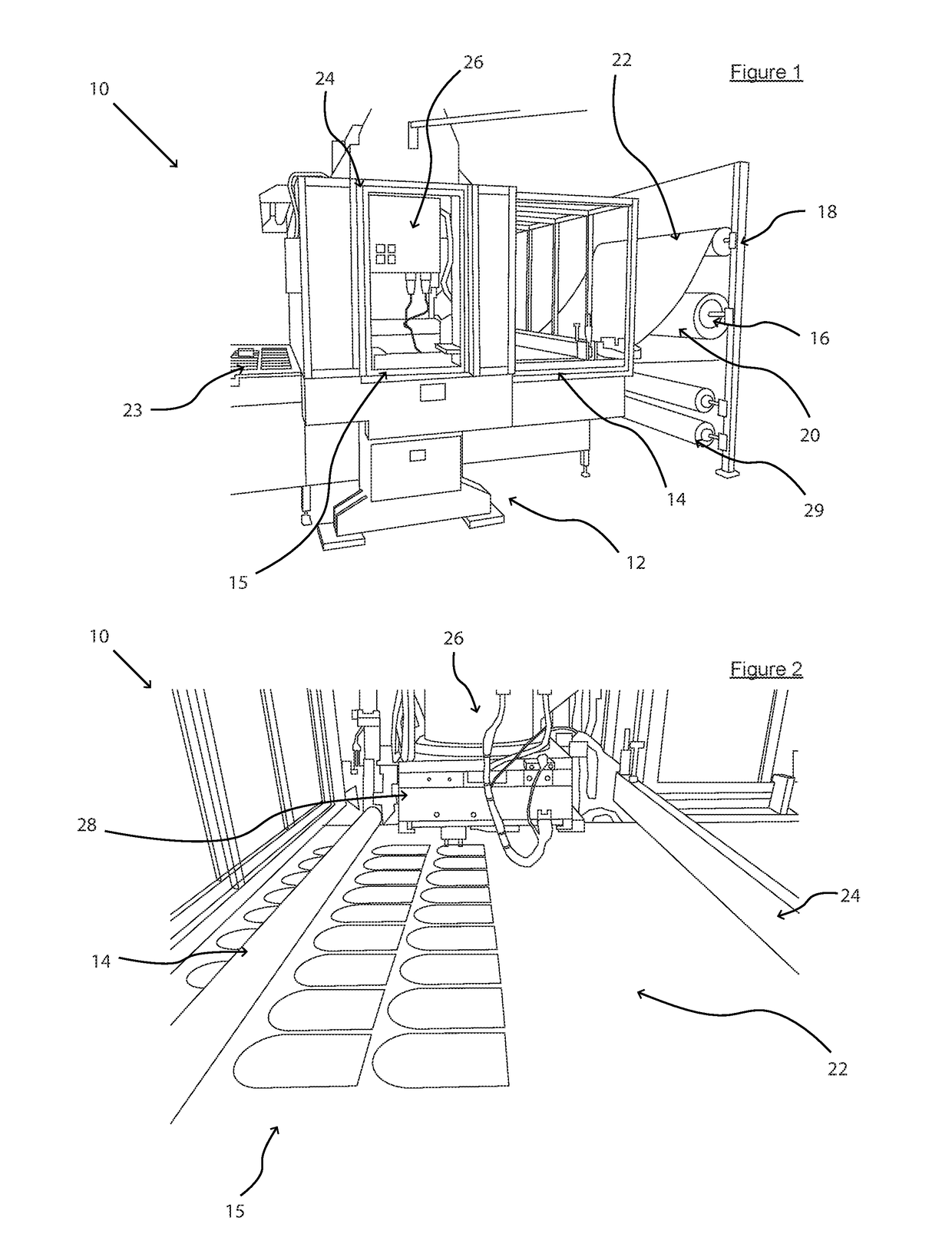
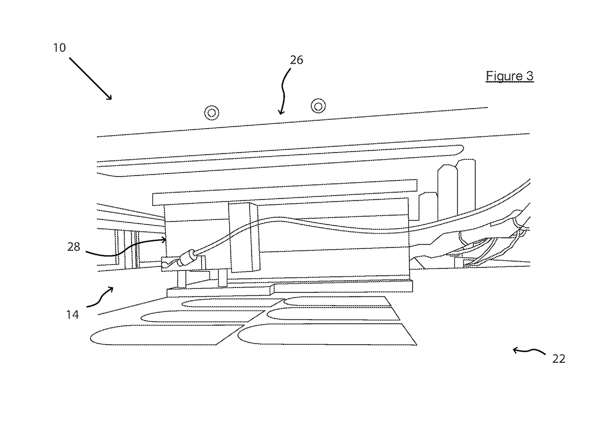
[0054]Referring firstly to FIGS. 1 to 3, there is shown an applicator mitt assembly system according to a preferred embodiment of the invention, indicated globally at 10, which is suitable for the production of applicator mitts, typically for the application of creams or lotions to a user.

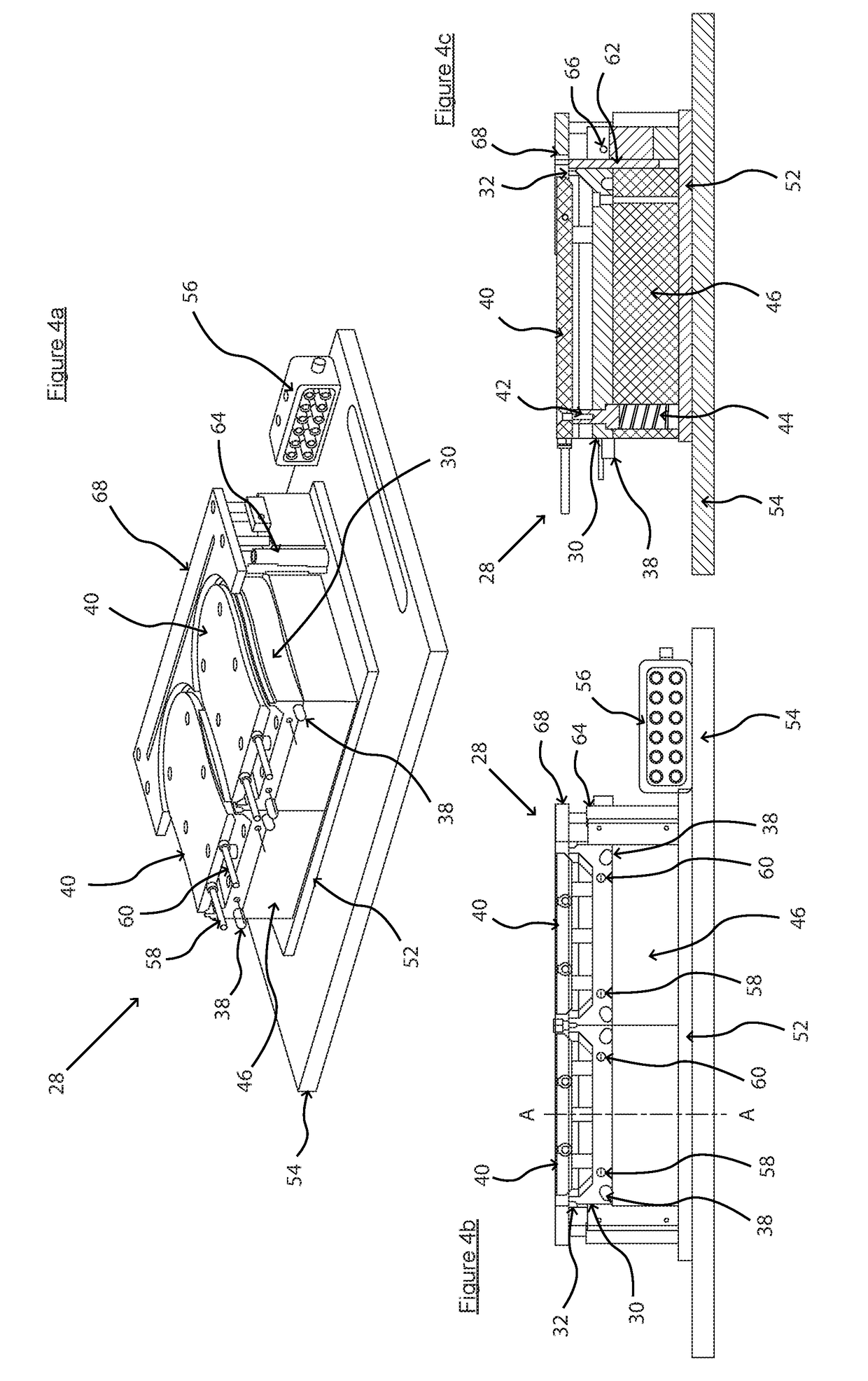
[0055]The applicator mitt assembly system 10 includes a frame 12, chassis or similar mounting structure to which is mounted a conveyor device 14, across which the necessary materials to be formed into applicator mitts can be fed. Such a conveyor device 14 may be formed as a belt-driven machine, or similarly operable device which is capable of feeding material through towards a cutting area, such as a flexible bed or roller or more preferably a ground, hardened steel cutting bed 15, as depicted. In the depicted system 10, the conveyor device 14 is an infeed conveyor fed by first and second material spools 16, 18, which respectively provide first and second material layers 20, 22 to be formed togethe...


PUM

PropertyMeasurementUnit
widthaaaaaaaaaa
shapeaaaaaaaaaa
perimeteraaaaaaaaaa

Abstract

An applicator mitt assembly system comprises an applicator mitt tooling including: a tooling body having a mitt-perimeter cutter and weld bead thereon which are shaped to a perimeter of an applicator mitt to be cut; a heating element associated with the tooling body, the heating element being shaped so as to match or substantially match a shape of the weld bead so as to create a perimeter weld for the applicator mitt when engaged with the tooling body; and an ejector platen which is actuatable relative to the tooling body to eject a cut and welded mitt away from the tooling body. The system can further comprise a conveyor device adapted to feed uncut and unwelded mitt material towards the applicator mitt tooling and a tooling actuator adapted to actuate the applicator mitt tooling relative to the conveyor device.

Description

CROSS REFERENCE TO RELATED APPLICATIONS[0001]This application claims priority to British Patent Application No. 1612964.5, filed Jul. 27, 2016, which is incorporated herein by reference.TECHNICAL FIELD OF INVENTION[0002]The present invention relates to an applicator mitt assembly system for the manufacture of applicator mitts particularly for the application of creams, lotions, foam mousses or sprays, such as tanning lotion. The invention also relates to an applicator mitt tooling for use in the system, a method of assembling an applicator mitt, and to an applicator mitt formed via the method.BACKGROUND OF INVENTION[0003]An applicator mitt is a glove-like item which has at least one surface which is suitable for the application of a tanning lotion to the body of a user, for instance, the surface typically being formed from a foam or spongiform material. Such applicator mitts are most commonly used in the application of tanning lotion.[0004]The applicator mitt must fulfil several req...

Claims


Application Information

Patent Timeline
Patent Type & Authority Patents(United States)
IPC IPC(8): A41D19/01B29C65/30B29C65/02A45D40/26B29C65/18B29C65/78B29C65/74A41D19/04B29C65/00B29D99/00A45D34/04B29L31/00B29L31/48
CPCB29C65/02A41D19/04A45D34/04A45D40/26B29C65/18B29C65/305B29C65/7441B29C65/787B29C65/7891B29C66/005B29C66/0062B29C66/1122B29C66/244B29C66/43B29C66/727B29C66/729B29C66/72343B29C66/7392B29C66/81419B29C66/81427B29C66/81821B29C66/8322B29C66/8432B29C66/91212B29C66/91231B29D99/0067A41D19/01Y10T156/1054B29C66/133B29C66/81417B29C66/863B29L2031/4864B29L2031/726B29C65/741B29C65/743B29C65/745B29C65/7461A61M35/10
Inventor COUND, TIMJONES, JEREMYTEECE, JOHN
Owner SYNLATEX
Why Eureka
Try Eureka