

Method of damping vibration, active hydraulic anti-vibration mount and vehicle including such a mount
a technology of active hydraulic anti-vibration and vibration damping, which is applied in the direction of vibration dampers, machine supports, machine frames, etc., can solve the problems of relative high frequency and relatively low amplitude, and achieve the effect of reducing the disadvantag
- Summary
- Abstract
- Description
- Claims
- Application Information
AI Technical Summary
Benefits of technology
Problems solved by technology
Method used
Image

Examples
first embodiment
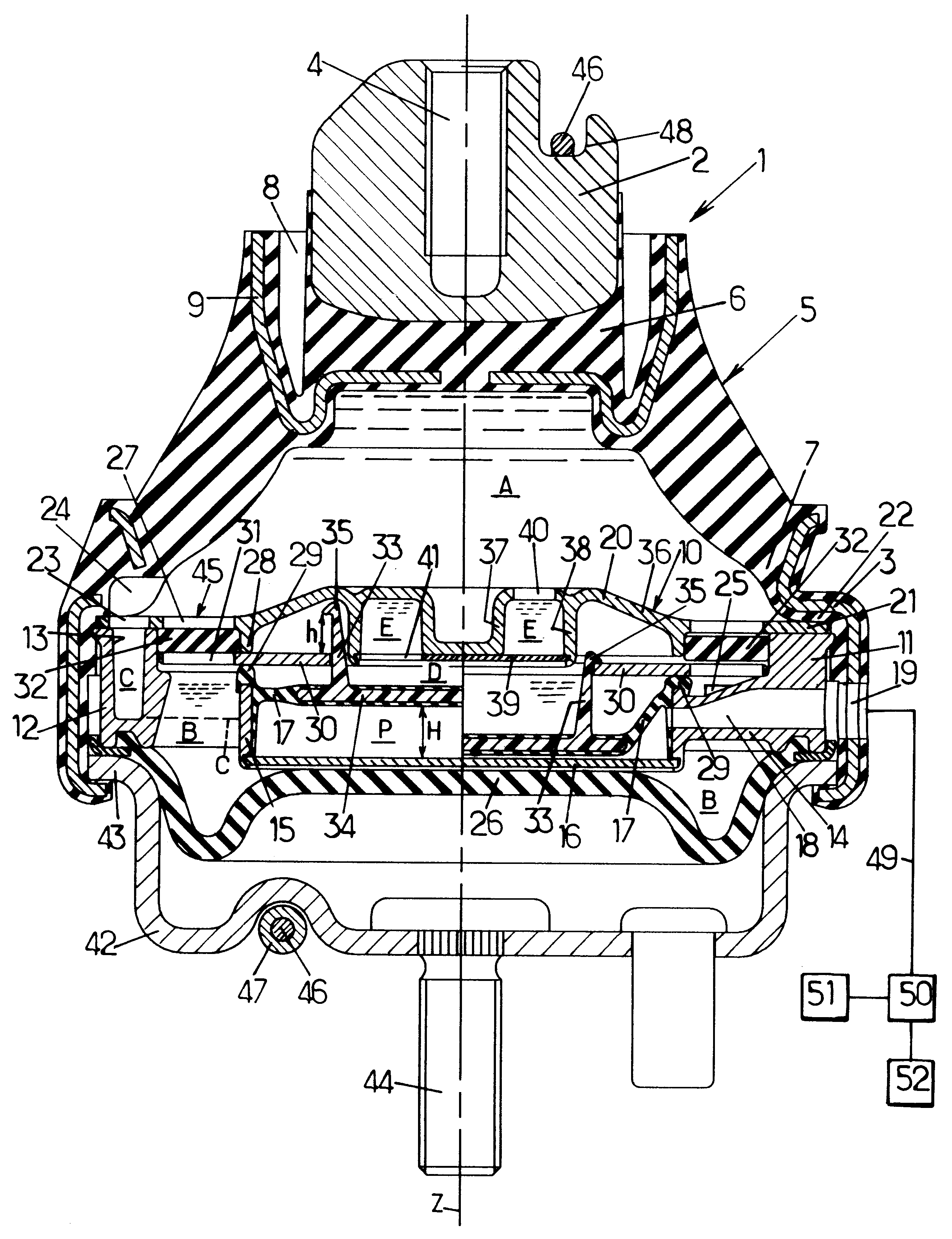
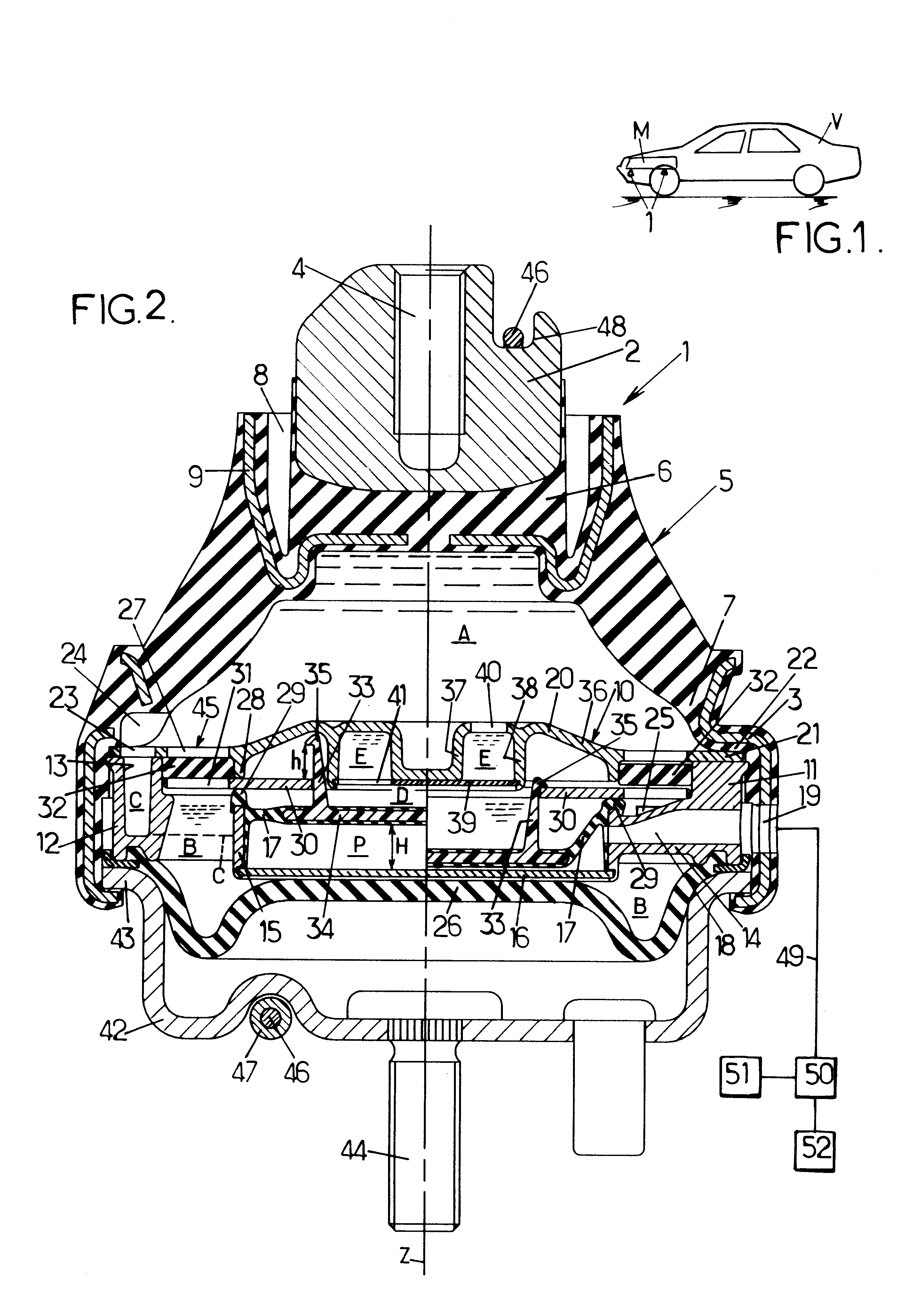
According to the invention, shown in FIG. 2, the hydraulic anti-vibration mount 1 includes first and second support elements 2,3 which are intended to be fixed respectively to the power unit M and the body V.
In the example considered the first support element 2 has the form of a plug centered on a vertical axis Z and having a threaded hole 4 enabling it to be attached to the power unit M, while the second support element is formed by a steel ring also centered on axis Z.
These two support elements 2,3 are connected by a relatively thick elastomer body 5 which has sufficient resistance to compression to absorb the static loads due to the weight of the power unit. This elastomer body 5 has a bell-shaped side wall extending between an apex portion 6 integrated with plug 2 and an annular base 7 integrated with ring 3.
Advantageously the apex 6 of the elastomer body has an annular recess 8 open at the top and surrounding the plug 2, or, if applicable, several recesses arranged angularly ar...
second embodiment
This second embodiment differs from the first simply in that
closing plate 39 is omitted,
the central portion 36 of the cover delimits a hollow space below it located at the center of collar 38, which engages with hooking fingers 33,
movable plate 30 cooperates with the cover 20 of the rigid partition to delimit the throttled passage E when said movable plate 30 is in its rest position, the movable plate including an orifice 53 which causes throttled passage E to communicate with intermediate chamber D (the contact between cover 20 and movable plate 30 no longer forms a seal when the vehicle is in the state of moving, as shown in the right-hand part of FIG. 2, but this is unimportant since there is then no or practically no exchange of liquid between intermediate chamber D and working chamber A).
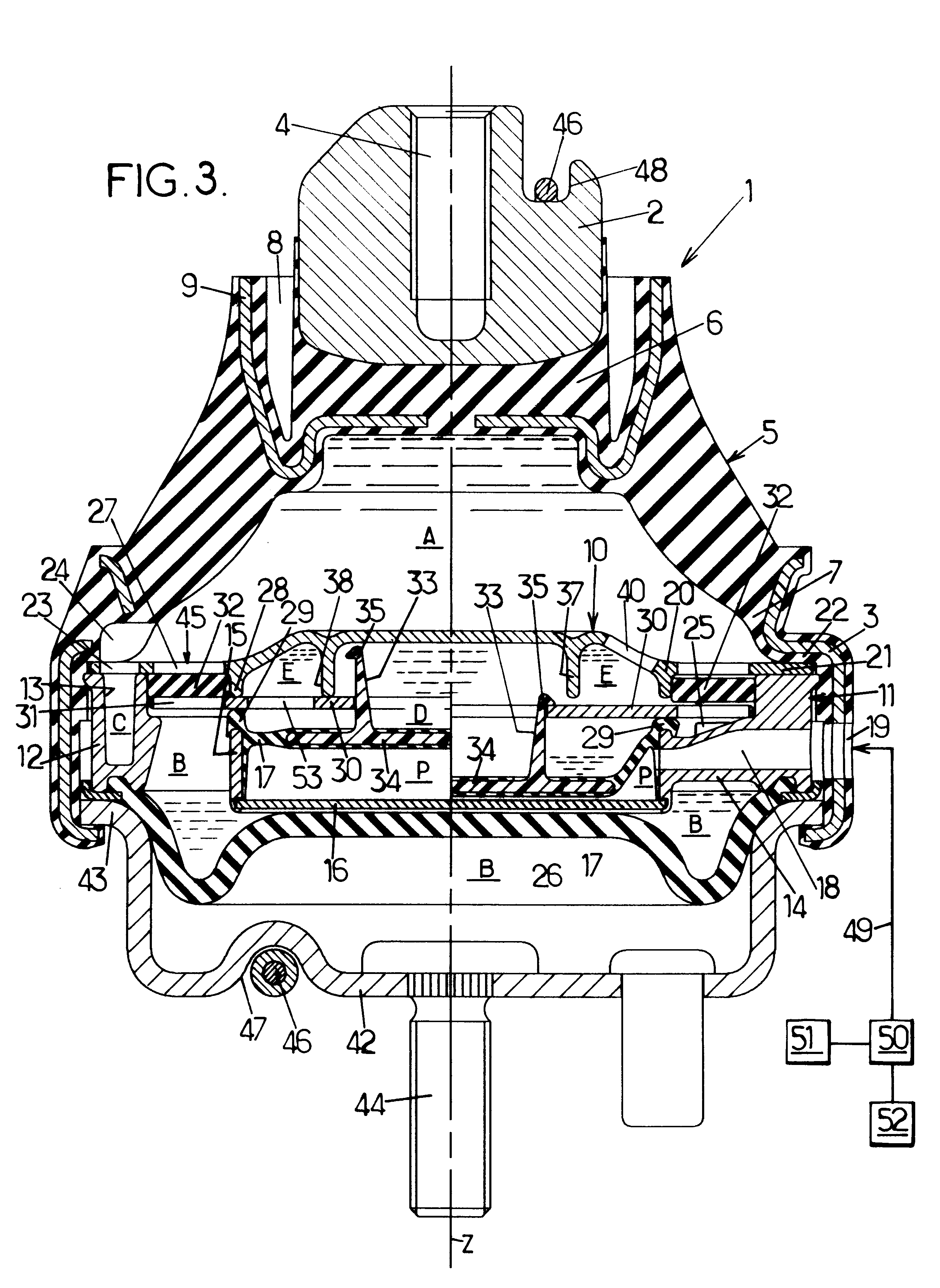
The third embodiment of the invention, represented in FIG. 4, is similar to the second embodiment described above, so that this third embodiment will not be described again in detail.
third embodiment
This third embodiment of the invention differs from the second embodiment by the following points:
plate 30 is immobilized axially by being clamped rigidly between collar 28 and a rigid reinforcing element 54 which reinforces the circumference of membrane 17, which membrane is no longer bonded to collar 15 but is simply held by axial clamping of support element 54 between collar 15 and plate 30,
membrane 17 no longer has the elastic bead 29 described earlier,
valve 32 is mounted with permanent free play between grids 27 and 31, this free play being sufficiently limited for amplitude .delta.V of the variations in the volume of working chamber A generated by the vibrations of valve 32 not to exceed 20% of the amplitude .DELTA.V of the variations in volume of the working chamber generated by the vibrations of membrane 17 when the engine is idling, so that valve 32 inhibits the counter-vibrations emitted by said membrane 17 to only a very limited degree,
reinforcing element 34 of membrane 1...
PUM
 Abstract
Description
Claims
Application Information