Reduced vibration printing press and method

a printing press and vibration reduction technology, applied in the field of printing presses, can solve the problems of reducing the life of the equipment, poor print quality, and significant side frame vibration of the printing unit tower

Inactive Publication Date: 2003-03-04
SHANGHAI ELECTRICGROUP CORP
View PDF9 Cites 19 Cited by
  • Summary
  • Abstract
  • Description
  • Claims
  • Application Information

AI Technical Summary

Benefits of technology

The present invention provides a method for reducing vibrations in a printing press having a first plate cylinder independently registrable from a second print cylinder. The first plate cylinder is operatively connected to at least one first laterally-moving vibrator roll and the second plate cylinder is operatively connected to at least one second laterally-moving vibrator roll. The method includes the steps of determining a lateral position of the first vibrator roll with respect to the second vibrator roll, and rotating the first plate cylinder with respect to the second plate cylinder so as to change the lateral position of the first vibrator roll with respect to the second vibrator roll.
By changing the lateral position of the first vibrator roll with respect to the second vibrator roll, and thus the phase between the vibrator rolls, a desired phase difference between the rolls corresponding to operation of the printing press at reduced vibrations can be achieved.

Problems solved by technology

Print unit towers have significant side frame vibration while starting up and during operation.
The vibrations caused by the vibrator rolls may reduce the life of the equipment and also may cause a lateral print double on the printed material, leading to poor print quality and, often, paper waste.
However, using separate motors to drive the vibrator rolls to produce the lateral motion incurs significant additional cost and complexity over the traditional technique of having the lateral and rotational motion of the vibrator rolls driven by the same drive which drives the printing cylinders.
When the lateral motion is driven by the same drive as a corresponding print cylinder, the phasing of the various vibrator rolls for different plate cylinders typically are not controlled, especially if independent motors drive the various plate cylinders.
If, for example, during a circumferential registration adjustment of one plate cylinder, the phase of the various vibrator rolls changes, those vibrator rolls may cause increased vibrations, leading to the defects mentioned above.
The dynamic dampener requires a separate device, which can be expensive and can be difficult to maintain.

Method used


Image

  • Reduced vibration printing press and method
  • Reduced vibration printing press and method
  • Reduced vibration printing press and method

Examples


Embodiment Construction

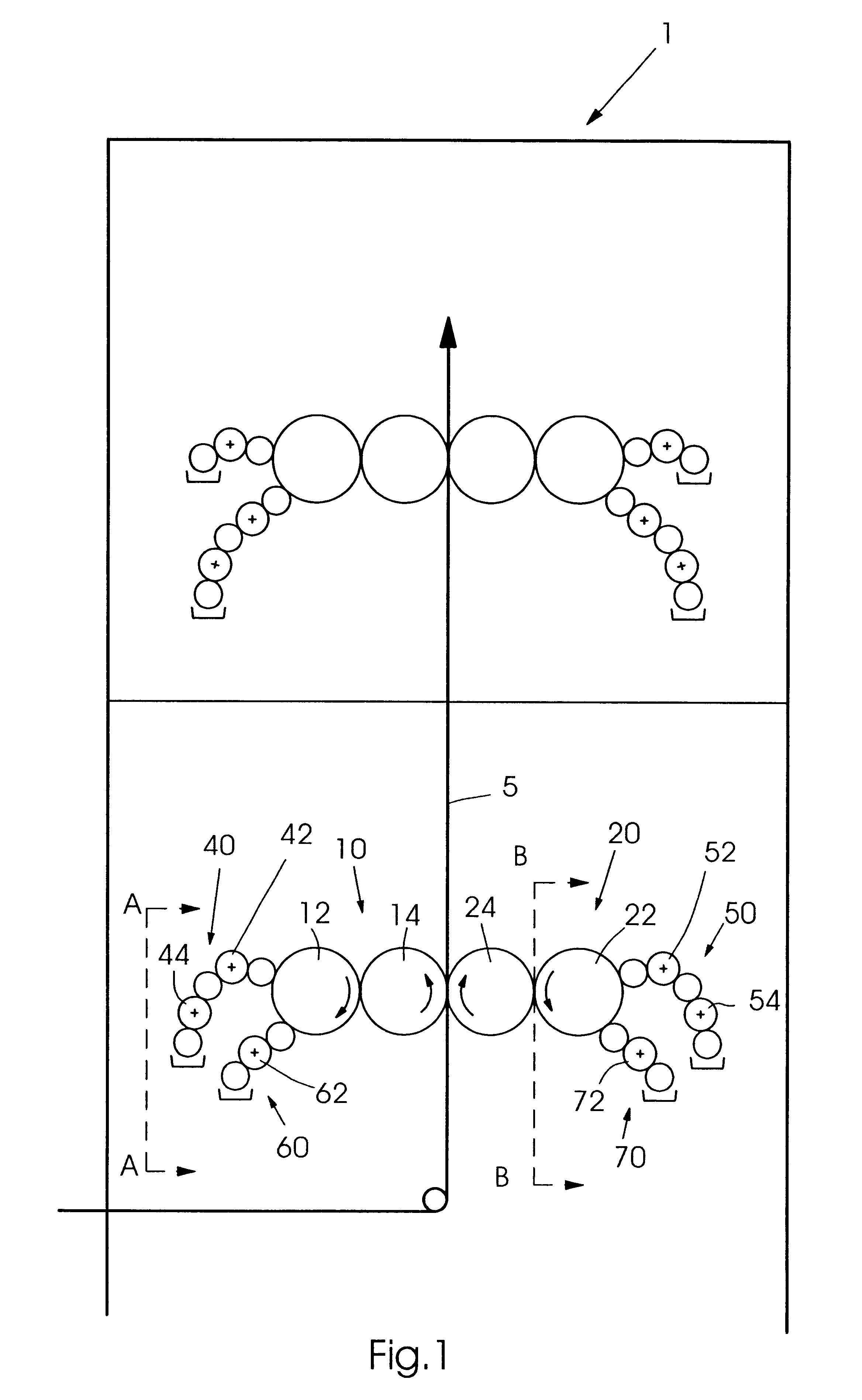
FIG. 1 shows an offset lithographic printing press 1 having a first print couple 10 and a second print couple 20. A web 5 passes between the print couples 10, 20 so as to be printed on both sides. Print couple 10 includes a plate cylinder 12 and a blanket cylinder 14. Plate cylinder 12 preferably includes a flat lithographic printing plate fastened in an axially-extending gap of the plate cylinder 12, although other forms of plate cylinders such as digitally-imaged plate cylinders are possible. Blanket cylinder 14 preferably includes an axially-removable tubular-shaped blanket. Print couple 20 similarly has a plate cylinder 22 and a blanket cylinder 24. Plate cylinder 22 is driven independently from plate cylinder 12.

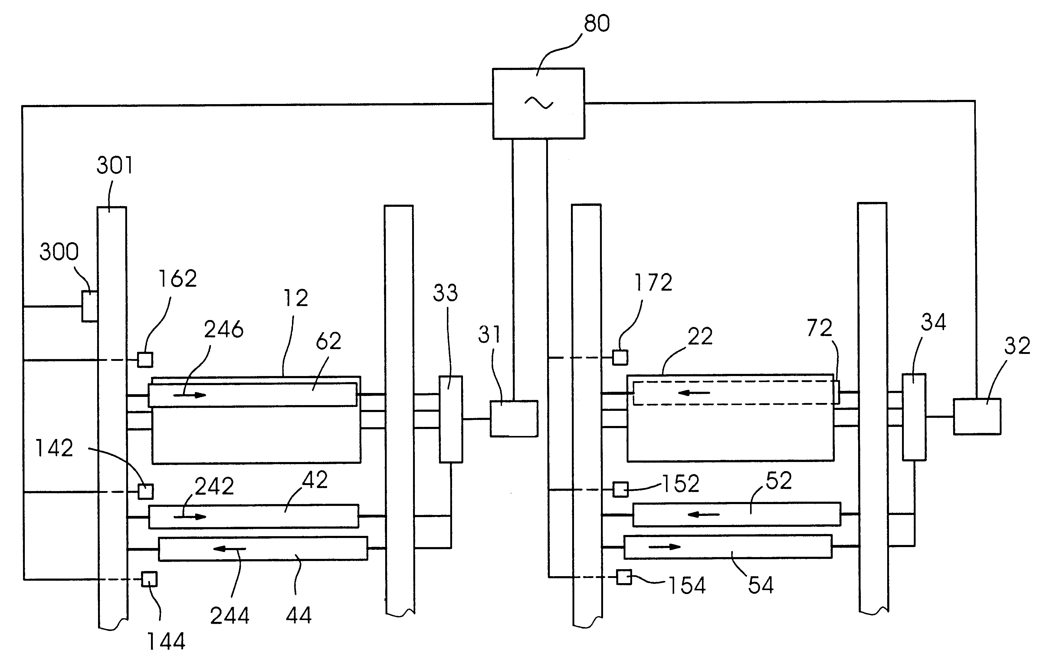
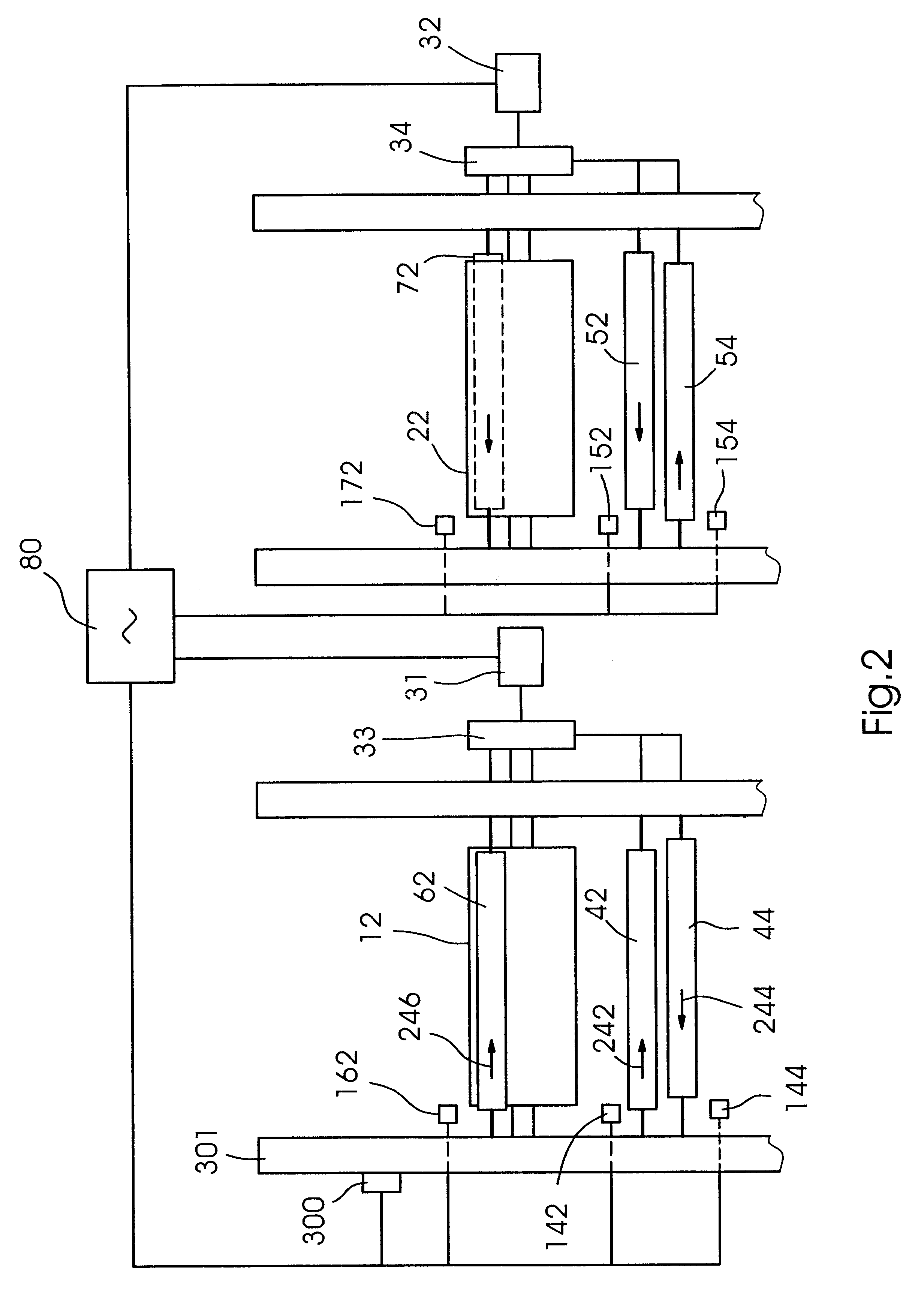
FIG. 2 shows views of printing press 1 through cross sections A--A and B--B as shown in FIG. 1, with only the vibration rollers of the inking and dampening units shown to improve clarity. A motor 31 and gearing 33 may drive plate cylinder 12, and blanket cylinder 14, wh...


PUM


Abstract

A method for reducing vibrations in a printing press, the printing press having a first plate cylinder independently registrable from a second print cylinder. The method includes the steps of determining a lateral position of the first vibrator, roll with respect to the second vibrator roll and rotating the first plate cylinder with respect to the second plate cylinder so as to change the lateral position of the first vibrator roll with respect to the second vibrator roll. A printing press has a controller receiving an input from at least one sensor, the controller rotating the first plate cylinder with respect to the second plate cylinder so as to alter a phase between the first vibrator roll and the second vibrator roll as a function of the input.

Description

1. Field of the InventionThe present invention relates generally to printing presses and more particularly to a printing press for operating with reduced vibrations.2. Background InformationPrint unit towers have significant side frame vibration while starting up and during operation. One of the major causes of side frame vibration are vibrator rolls, which move laterally so as to provide a more consistent ink coating or dampening solution to a plate cylinder. The vibrations caused by the vibrator rolls may reduce the life of the equipment and also may cause a lateral print double on the printed material, leading to poor print quality and, often, paper waste.Prior attempts to reduce vibrator roll vibration effects include using a separate motor to drive the lateral motion of the vibrator rolls so that the torque disturbances due to vibrator oscillation can be insulated from the unit drive, or to drive the lateral motion so that vibrator phases can be adjusted relative to one another...

Claims


Application Information

Patent Timeline
Patent Type & Authority Patents(United States)
IPC IPC(8): B41F13/08B41F31/00B41F31/15
CPCB41F13/085B41F31/15Y10S101/38B41P2213/734Y10S101/32B41P2213/42
Inventor DOUILLARD, GERALD ROGERDUMAIS, MARK BERNARDWORONIAK, MICHAEL THOMAS
Owner SHANGHAI ELECTRICGROUP CORP
Why Eureka
Try Eureka