Actuating drive with an electric motor and control electronics

a technology of electric motors and drives, applied in the direction of generators/motors, connection contact materials, coupling device connections, etc., can solve the problem that electric motors cannot be operated

Inactive Publication Date: 2003-03-04
ROBERT BOSCH GMBH
View PDF12 Cites 47 Cited by
  • Summary
  • Abstract
  • Description
  • Claims
  • Application Information

AI Technical Summary

Problems solved by technology

In such a connection of the electric motor housing to a brush, there is most often the limitation that the electric motor can only be operated in one rotation di

Method used


Image

  • Actuating drive with an electric motor and control electronics
  • Actuating drive with an electric motor and control electronics
  • Actuating drive with an electric motor and control electronics

Examples


second exemplary embodiment

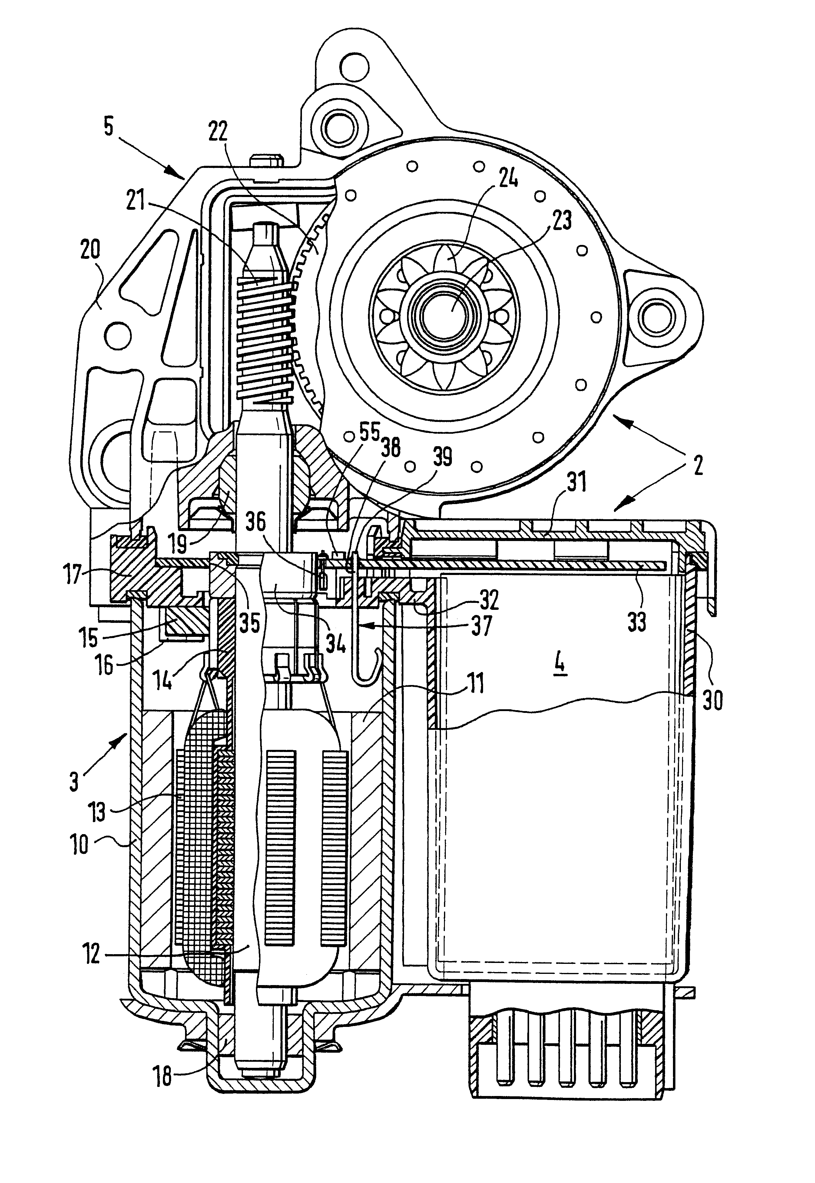
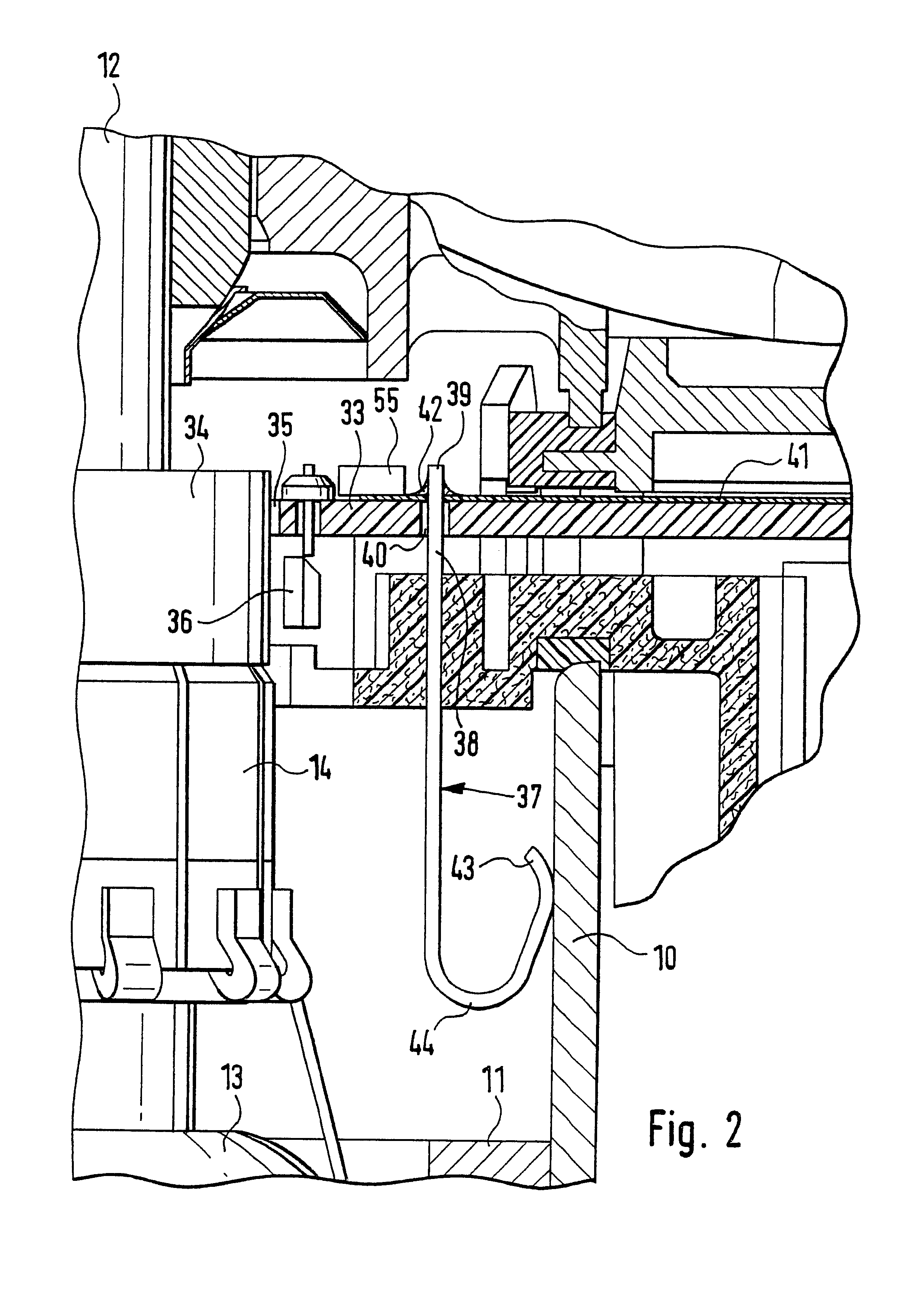
The second exemplary embodiment according to FIGS. 3 and 4 differs from the exemplary embodiment according to FIGS. 1 and 2 by virtue of the fact that a positively engaging, materially adhesive injection molding of the contact spring 37 is eliminated. In contrast, a conduit 45 is simply provided in a modified brush carrying plate 17a. A contact spring 37a that is modified through the addition of two resilient tabs 46 and 47 is slid through this conduit 45. The securing tabs 46 and 47 are made out of the material of the contact spring 37a and can be formed by producing U-shaped slits and bending material out from the contour of the contact spring 37a. Since the insertion of the contact spring 37a into the conduit 45 with the soldering tabs 39 takes place ahead of time, the securing tab 46 can already protrude out from the contour of the contact spring 37a as shown in FIG. 3. There are two possibilities for the securing tab 47. The first possibility is comprised of allowing the resili...


PUM


Abstract

An actuating drive with an electric motor that has a metallic electric motor housing, a shaft, an armature, collector, brushes, and a brush holder plate, and control electronics. Electronic and electric components are connected to a printed circuit board and the printed circuit board protrudes at right angles to the shaft and into a cross section of the electric motor housing. Outside the electric motor housing, the electronic and electric components are protected by a control electronics housing. Radio interference suppression means, for example, can be disposed inside the actuating drive. The system includes a printed circuit board with a strip conductor and a contact spring that leads from the strip conductor and this contact spring protrudes into the electric motor housing, wherein a resilient free end of the spring rests against the electric motor housing producing an electrical contact.

Description

PRIOR ARTThe invention is based on an actuating drive with an electric motor and control electronics.By means of the references U.S. Pat. No. 4,384,223, DE 33 14 412 C2, and DE 196 54 352 A1, it is widely known to dispose electrical interference suppression means inside metallic electric motor housings, adjacent to the collectors and associated brushes of so-called collector motors, and to connect these interference suppression means to the brushes and also to the metallic electric motor housings. In order to connect the interference suppression means to the metallic electric motor housings, resilient tabs protrude from so-called brush holder plates that support the brush holders and these tabs can, for example, be embodied at their free ends in the form of tapering claws. This has the advantage that a favorable electrical contact is produced, for example through the production of scoring tracks due to relative movements of these claws in relation to the electric motor housing durin...

Claims


Application Information

Patent Timeline
IPC IPC(8): H02K11/02H02K7/116H02K11/00H02K5/14H02K11/22H02K11/40H02K13/00
CPCH02K11/00H02K11/022H02K11/0089H02K7/1166Y10S310/06H02K11/40H02K11/0141H02K11/02
Inventor MOSKOB, FRANK
Owner ROBERT BOSCH GMBH
Why Eureka
Try Eureka