Packing means for small form-factor module

a pluggable, small technology, applied in the direction of fixed connections, coupling device connections, instruments, etc., can solve the problems of liable dislodging of firm engagement between first and second covers,

Inactive Publication Date: 2003-03-11
HON HAI PRECISION IND CO LTD
View PDF5 Cites 65 Cited by
  • Summary
  • Abstract
  • Description
  • Claims
  • Application Information

AI Technical Summary

Problems solved by technology

Unfortunately, engagement between the first and second covers is

Method used


Image

  • Packing means for small form-factor module
  • Packing means for small form-factor module
  • Packing means for small form-factor module

Examples


Embodiment Construction

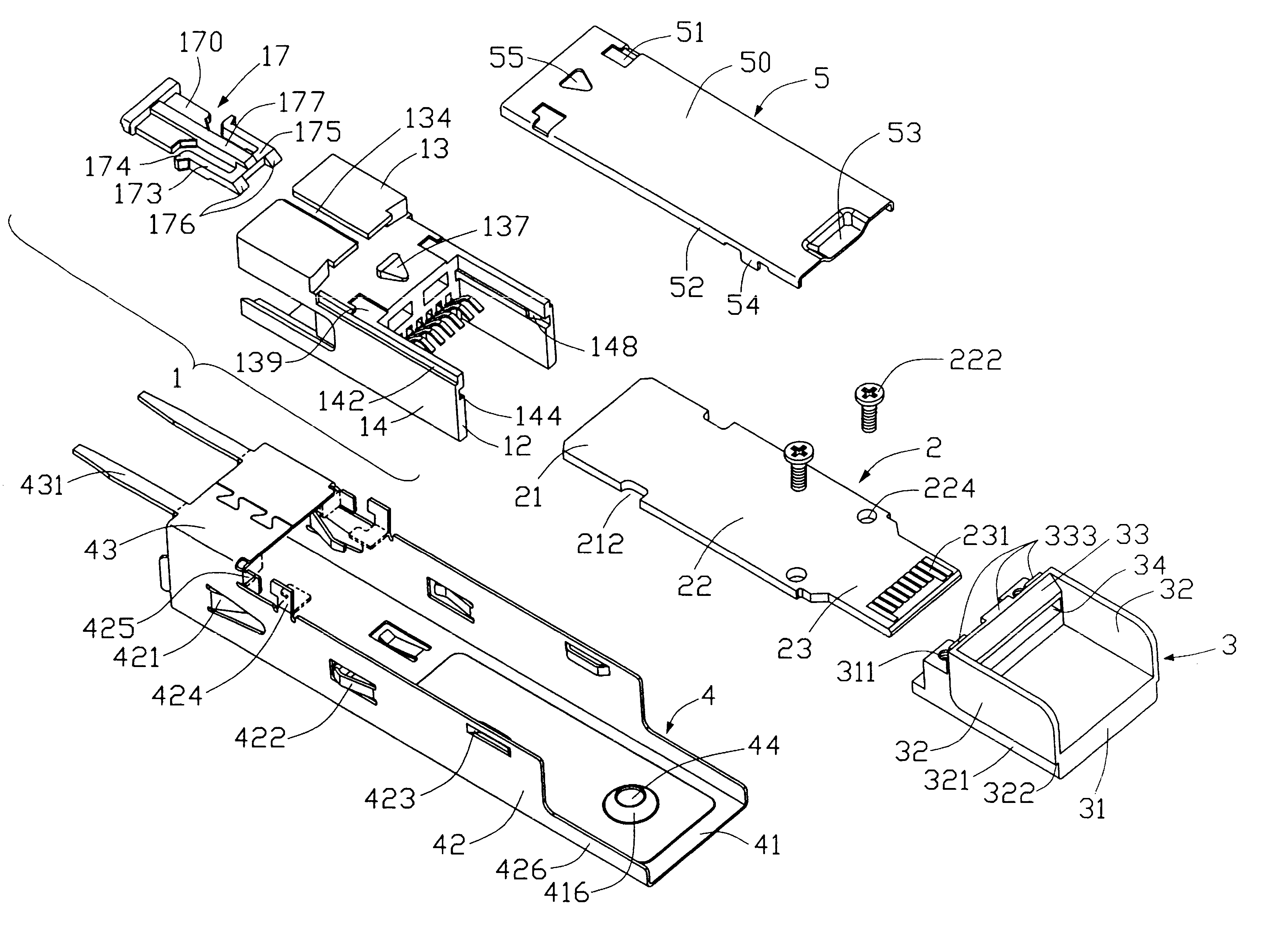
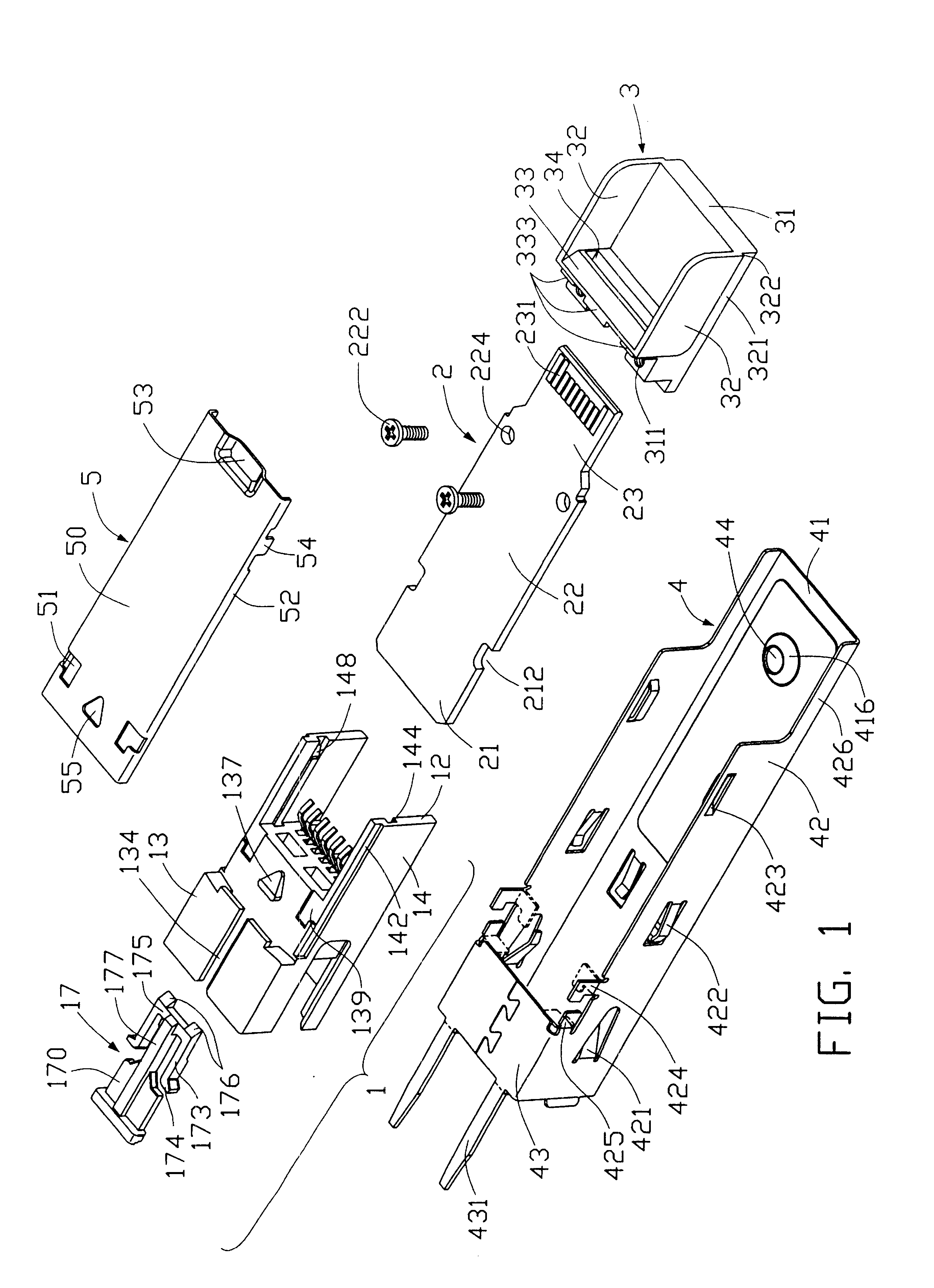
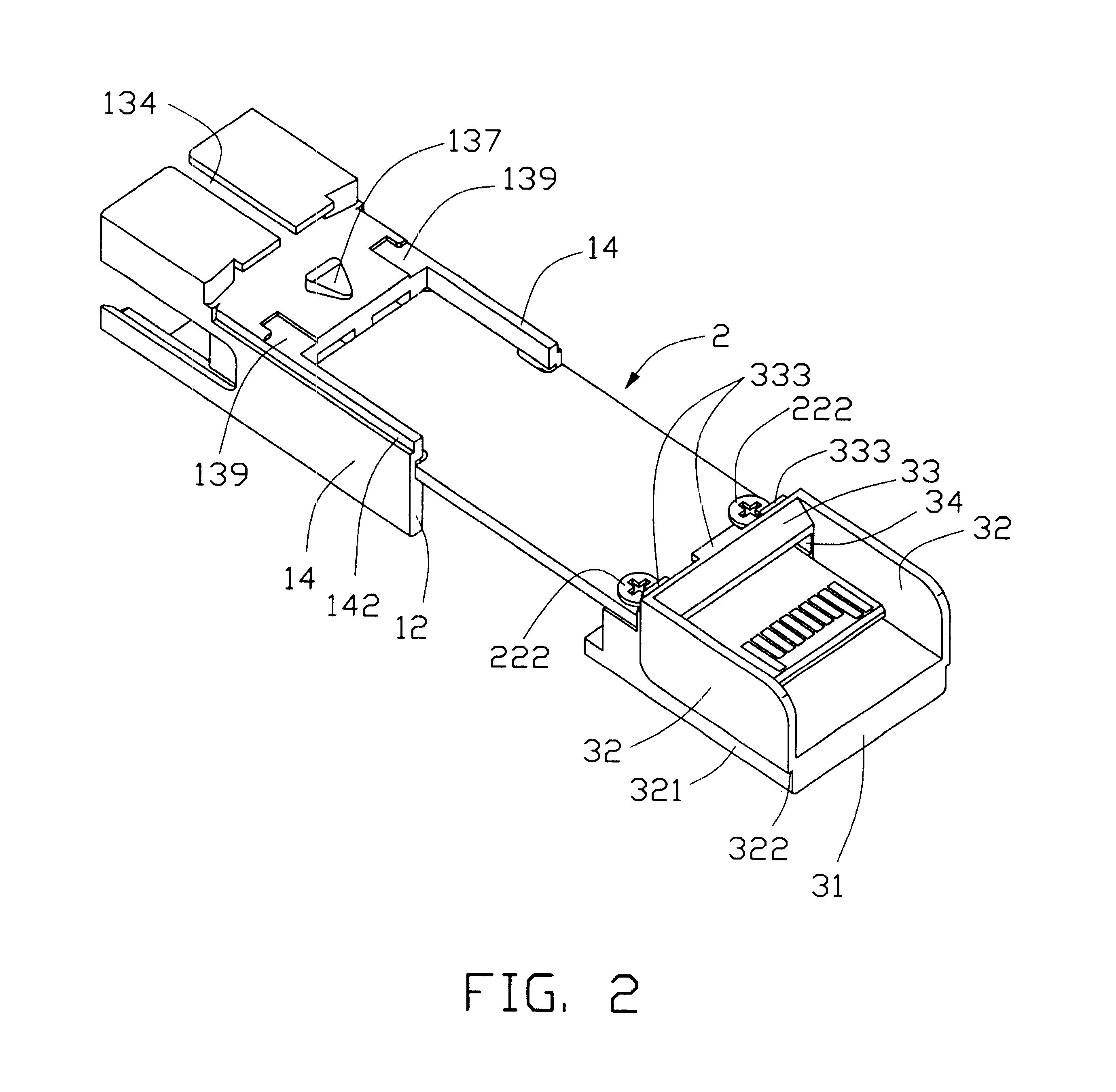
Referring to FIG. 1, a small form-factor pluggable (SFP) module assembly in accordance with the present invention comprises a housing 1, a printed circuit board (PCB) 2, a base 3, an upper cover 4 and a lower cover 5. The PCB 2 is retained by and between the housing 1 and the base 3. The upper and lower covers 4, 5 cooperatively form an enclosure that encases the housing 1, the PCB 2 and the base 3 therein.

Referring to FIGS. 1, 3 and 4, the housing 1 is generally made of plastic material. The housing 1 comprises a front end 11, a rear end 12, a lower portion 13, two parallel and opposite sidewalls 14 extending generally upwardly from the lower portion 13, a bracket 15, an upper portion 16, and an ejector 17. The bracket 15 is integrally enclosed by the lower portion 13, the sidewalls 14 and the upper portion 16. A front section of the lower portion 13 forms an ejector seat 132. A longitudinal guide slot 134 is defined in a front middle portion of the ejector seat 132. The ejector se...


PUM


Abstract

Means to firmly pack an SFP module. The means comprises an upper cover (4) and a lower cover (5). The upper cover comprises an upper plate (41), two sidewalls (42) integrally depending from the upper plate, and a bottom plate (43) formed between front portions of the sidewalls. The lower cover has a main panel (50). A pair of flanges (52) extends from opposite longitudinal sides of the main panel respectively. Two elbow-shaped locking tabs (424) integrally depend from respective opposite bottom edges of the sidewalls of the upper cover. A pair of symmetric elbow-shaped cutouts (51) is respectively defined in opposite sides of a front portion of the lower cover, for extension of the elbow-shaped locking tabs of the upper cover therethrough.

Description

1. Field of the InventionThe present invention relates to small form-factor pluggable (SFP) modules, and more particularly to means for firmly and securely packing such modules.2. Description of Related ArtNowadays SFP transceivers are being more and more widely used for bi-directional transmission of data between an electrical interface and an optical data link. An SFP transceiver receives electrically encoded data signals, converts them into optical signals, and transmits the optical signals over the optical data link. The SFP transceiver also receives optically encoded data signals, converts them into electrical signals, and transmits the electrical signals onto the electrical interface.U.S. Pat. No. 6,178,096 discloses an SFP transceiver module. The SFP module is encased in an enclosure which comprises first and second covers made of electrically conductive material. Each first and second cover has a generally planar main wall parallel to and spaced from a printed circuit board ...

Claims


Application Information

Patent Timeline
IPC IPC(8): G02B6/42H01R13/658H01R13/633H01R12/50H01R13/6582
CPCH01R13/6582G02B6/4246H01R23/7073H01R13/633H01R12/722G02B6/4261G02B6/4284G02B6/428
Inventor HWANG, JENQ-YIH
Owner HON HAI PRECISION IND CO LTD
Why Eureka
Try Eureka