Method for packaging glass-silicon wafer-grade chiponboard (COB) of light emitting diode (LED)

A light-emitting diode, chip packaging technology, applied in electrical components, electrical solid devices, circuits, etc., can solve the problems of poor moisture resistance of organic substances, poor light transmittance of lenses, poor light transmittance performance, etc. The effect of strong resistance to high temperature and high temperature

Active Publication Date: 2011-06-15
SOUTHEAST UNIV
View PDF5 Cites 12 Cited by
  • Summary
  • Abstract
  • Description
  • Claims
  • Application Information

AI Technical Summary

Problems solved by technology

Transparent organic glue such as epoxy resin is widely used in the preparation of light-emitting diode (LED) lenses, but the lens made of organic glue has poor light transmission and unstable properties. The light performance becomes poor, and the moisture resistance of organic matter is poor
[0004] The phosphor coating of light-emitting diodes (LEDs) is mostly applied by dispensing glue (silica gel mixed with phosphor powder) on the chip, so that the efficiency of phosphor coating is very low; and the packaging of the chip also uses glue dispensing. The curing method is packaged one by one, and a special reflective cup needs to be installed to increase the light output rate
This method of monolithic packaging is very inefficient, so if wafer-level phosphor coating and packaging can be performed to reduce packaging steps, efficiency will be greatly improved and costs will be reduced

Method used


Image

  • Method for packaging glass-silicon wafer-grade chiponboard (COB) of light emitting diode (LED)
  • Method for packaging glass-silicon wafer-grade chiponboard (COB) of light emitting diode (LED)
  • Method for packaging glass-silicon wafer-grade chiponboard (COB) of light emitting diode (LED)

Examples


Embodiment 1

[0039] A wafer-level glass bulb cavity packaging method for light-emitting diodes, comprising the following steps:

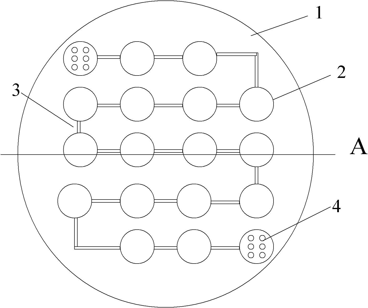
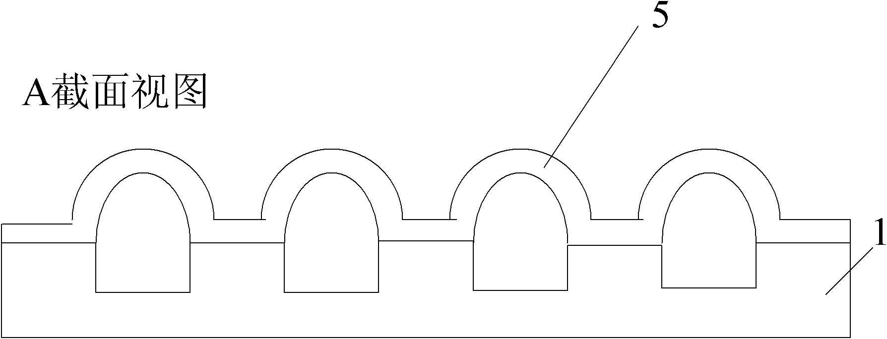
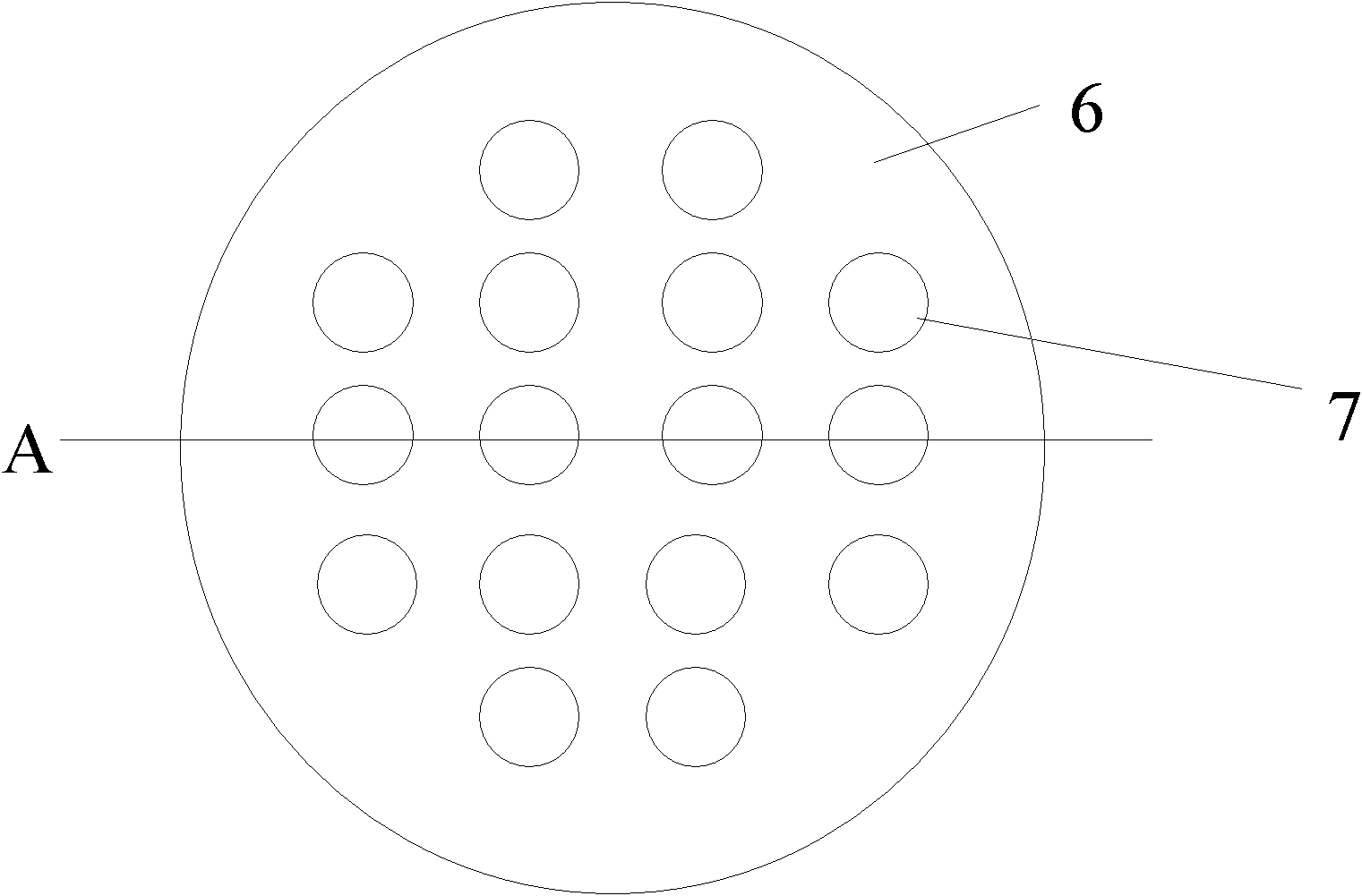
[0040] The first step is to use Si micromachining technology to etch specific microgrooves and microchannel patterns on Si wafers (such as 4-inch wafers), and the patterns corresponding to the packaged LED arrays: microgroove arrays, microgrooves The micro-grooves are connected by micro-channels, the micro-grooves are square or circular, the size ratio of micro-grooves and micro-channels is adjusted according to the preparation requirements, and an appropriate amount of heat release agent is placed in the micro-grooves; in the second step, the patterned The above-mentioned Si wafer and the Pyrex7740 borosilicate glass wafer with thermal air release agent are anodically bonded in air or vacuum, so that the above-mentioned microgroove and micro-channel are sealed to form a sealed cavity; the third step is to bond the above-mentioned The combined wafer is heated to...

Embodiment 2

[0043] A wafer-level glass bulb cavity packaging method for light-emitting diodes, comprising the following steps:

[0044] The first step is to use the Si micromachining process to etch the wet pattern corresponding to the packaged LED array on the Si wafer (such as a 4-inch wafer): a micro-groove array (80um in depth), and the micro-grooves are separated by micro-grooves. The flow channels are connected, the micro-groove is circular, and an appropriate amount of heat-releasing agent calcium carbonate is placed in the micro-groove;

[0045] In the second step, the above-mentioned Si wafer with a pattern and a thermal air release agent is anodically bonded to the Pyrex7740 glass wafer in a vacuum, so that the Pyrex7740 glass forms a sealed cavity with the above-mentioned microgrooves and microflow channels;

[0046] The third step is to heat the above-bonded wafers to 880°C in the air and keep it warm for 10 minutes. The heat release agent calcium carbonate will generate posit...

Embodiment 3

[0053] A method for manufacturing a wafer-level glass microcavity for LED packaging, comprising the following steps:

[0054] The first step is to oxidize a 5000A oxide layer on a single-sided polished silicon wafer by a combination of dry and wet oxygen, spin-coat AZ P4620 photoresist on the polished surface, expose and develop to remove the photoresist that needs to be etched on the surface of the microgroove. Use Si micromachining technology to etch shallow grooves on Si wafers (such as 4-inch wafers). The silicon wafers used can be silicon wafers with a standard thickness, such as 500 micron thick silicon wafers. The shallow grooves are etched by TMAH wet etching. For etching, heat in a water bath at 90°C for 2 to 2.5 hours, and the etching depth is 80 to 120. This depth can be relatively easy to build a high-temperature air release agent, and can provide a certain space between the high-temperature air release agent and the wafer to avoid contact with the glass. The conta...


PUM


Abstract

The invention discloses a method for packaging a glass-silicon wafer-grade chiponboard (COB) of a light emitting diode (LED). The method comprises the following steps: 1, etching a silicon micro slot array with the micro slots communicated with each other through micro channels, and placing a proper amount of heat outgas agent in the micro slots; 2, performing anodic bonding on the Si wafer with patterns and the heat outgas agent and borosilicate glass wafer in air or in vacuum to form a sealed cavity; 3, heating and preserving heat to form a spherical glass micro cavity, cooling the cavity to normal temperature, annealing and removing silicon to obtain a wafer-grade glass micro cavity; 4, preparing a lead substrate; 5, mounting a chip and leading a wire; 6, carrying out wafer-grade bonding; and 7, filling silica gel to realize the wafer-grade packaging of the LED. By achieving the integration with the wafer-grade LED reflecting cup, the method reduces heat resistance and cost.

Description

technical field [0001] The invention relates to a MEMS (micro-electro-mechanical system) packaging technology, in particular to a glass-silicon wafer-level chip on board (COB) packaging method for a light-emitting diode. Background technique [0002] For lighting purposes, high-power white light-emitting diodes (LEDs) have been widely concerned by scientific research and enterprises. In order to generate sufficient light intensity, the working current of light-emitting diodes (LEDs) must be as large as possible, and the large working current is required for the packaging of light-emitting diodes (LEDs). The heat dissipation problem of the system has brought serious challenges. Therefore, by designing the optical packaging structure of white light-emitting diodes (LEDs) and increasing their light output rate, sufficient light intensity can be obtained under a certain current, and the lens can be used to improve the collimation of the beam, so light-emitting diodes (LEDs) The...

Claims


Application Information

Patent Timeline
Patent Type & Authority Applications(China)
IPC IPC(8): H01L33/00H01L33/48H01L33/56H01L33/54H01L33/58H01L33/60H01L33/62
CPCH01L2224/45144H01L2224/48091
Inventor 尚金堂徐超陈波寅张迪
Owner SOUTHEAST UNIV
Why Eureka
Try Eureka