DC power supply with output voltage detection and control

a technology of output voltage and power supply, applied in the direction of power supply lines, power conversion systems, instruments, etc., can solve the problems of reducing the capacity of the capacitor c1 the greater overshoot and the greater undershoot, and the inability to increase the base current immediately

Inactive Publication Date: 2003-03-11
DENSO CORP
View PDF5 Cites 11 Cited by
  • Summary
  • Abstract
  • Description
  • Claims
  • Application Information

AI Technical Summary

Problems solved by technology

After the output voltage Vo decreases to the target of the output voltage Vo, the base current cannot be increased immediately due to the delay in the operational amplifier.
In this operation, there is the tendency that the lower the capacity of the capacitor C1 the greater overshoot and the greater undershoot.

Method used


Image

  • DC power supply with output voltage detection and control
  • DC power supply with output voltage detection and control
  • DC power supply with output voltage detection and control

Examples


first embodiment

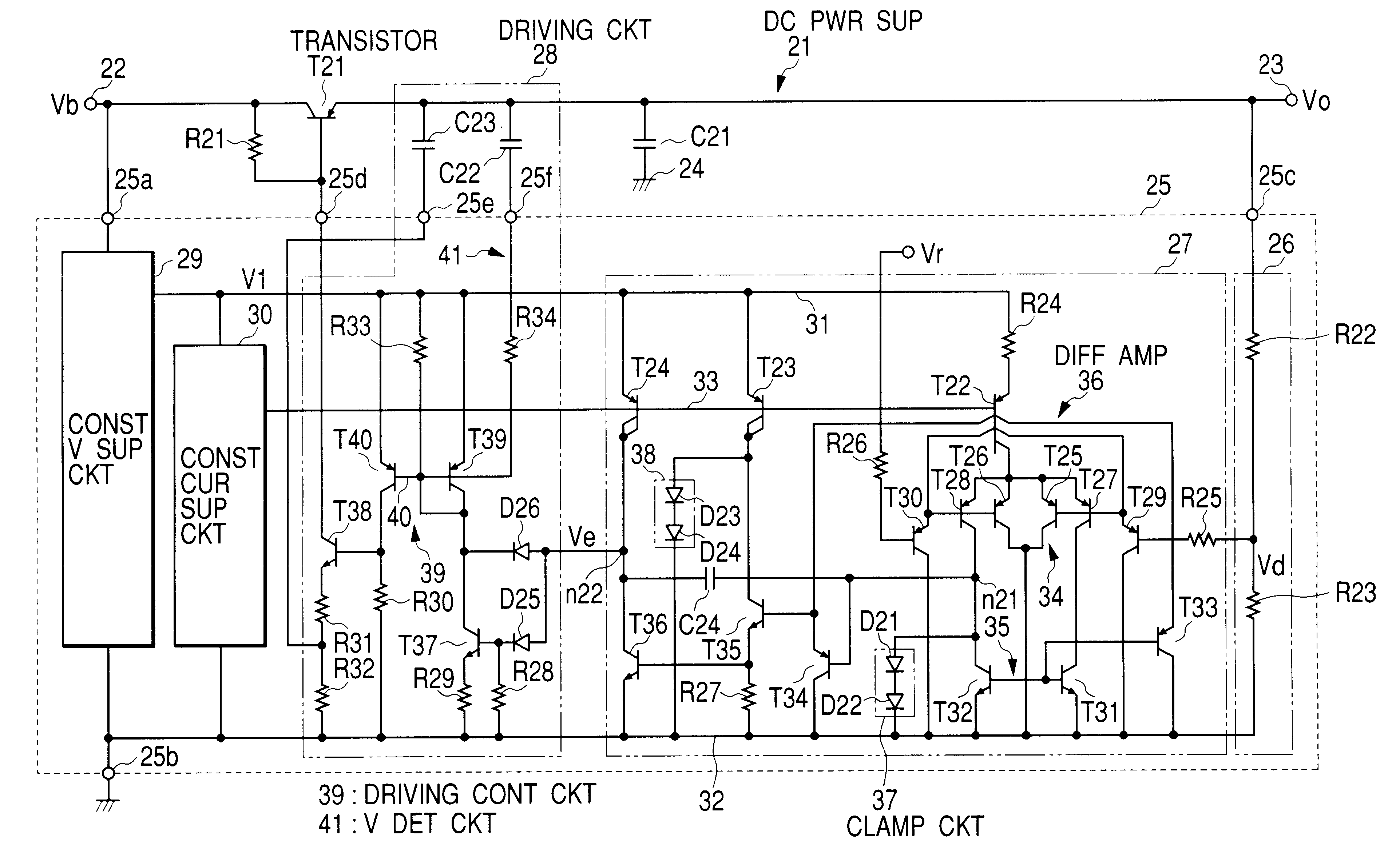
FIG. 1 is a schematic circuit diagram of a series type of a dc power supply 21 according to a

The dc power supply 21 is used in an engine control electronic control unit (engine control ECU) for an automobile vehicle for example. The input terminal 22 of the dc power supply 21 is supplied with a battery voltage Vb as an input voltage (for example, 14 V) from a positive terminal of a battery (not shown) through an ignition switch (not shown). The output terminal 23 of the dc power supply 21 is connected to the engine control ECU as a load to supply the output voltage Vo (for example 5 V) thereto.

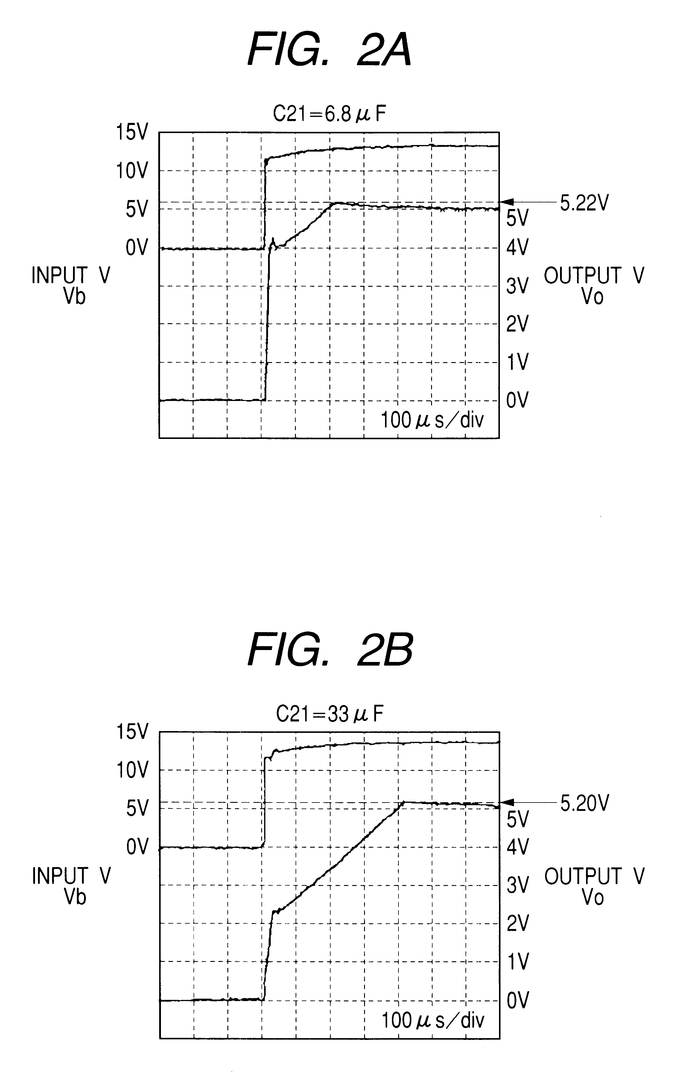
The dc power supply 21 is of a series type, and thus, a PNP transistor T21 is connected between the input 22 and the output 23. More specifically, the emitter of the transistor T21 is connected to the input terminal 22 and the collector of the transistor T21 is connected to the output terminal 23. A resistor R21 is connected between the base and the emitter of the transistor T21. A smoothing c...

second embodiment

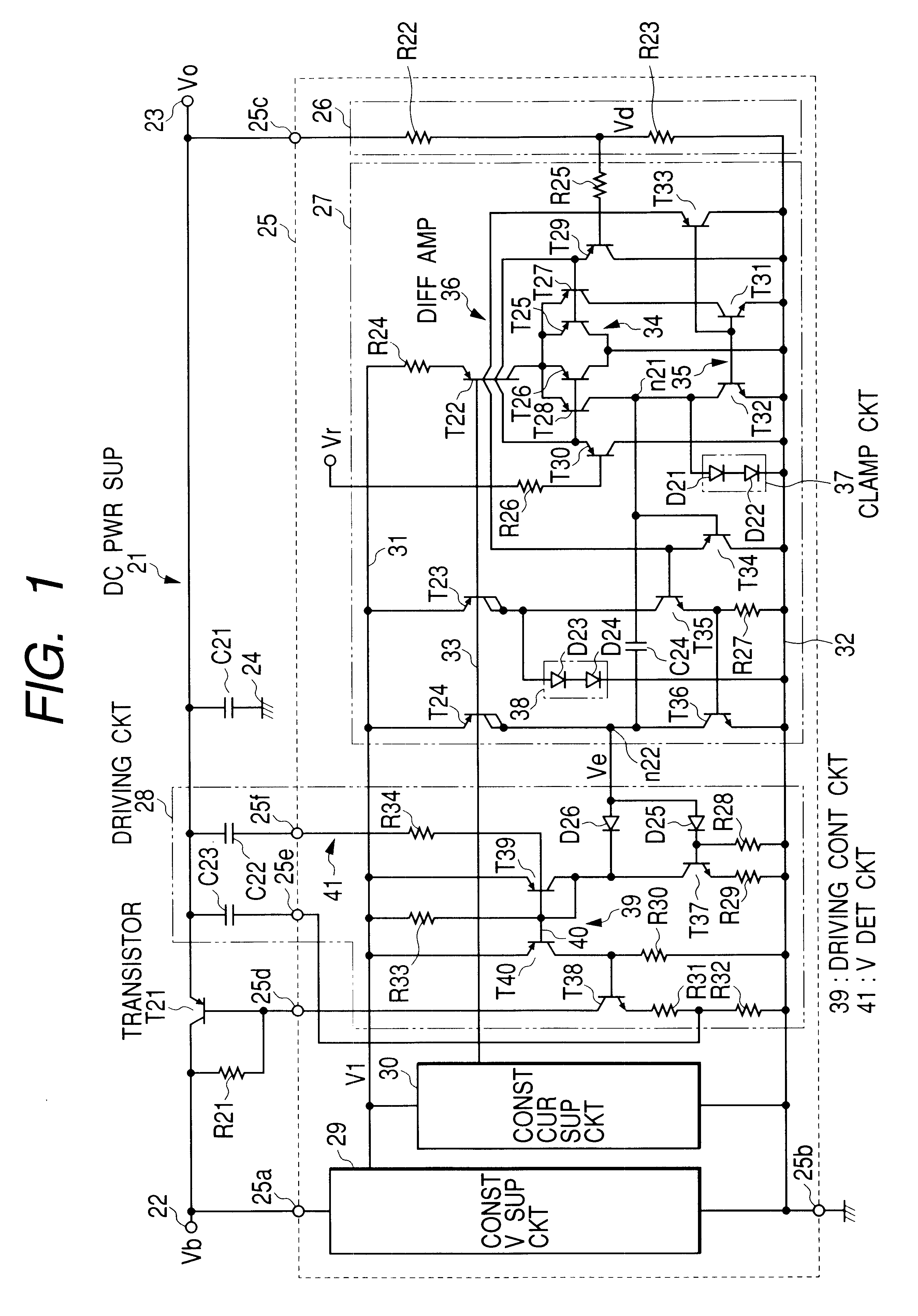
FIGS. 3 and 4 are schematic circuit diagrams of the dc power supply according to the second embodiment, wherein the circuit shown in FIG. 3 is connected to the circuit shown in FIG. 4 through lines indicated by references (a) to (g).

The dc power supply according to the second embodiment has the substantially the same structure as that of the first embodiment. The difference is that an input voltage detection circuit 45, a delay control circuit 46, and a switch circuit 47 are further provided.

In the driving circuit 44, the switch circuit 47 is connected between the collector of the transistor T40 and the base of the transistor T38. The switch circuit 47 includes transistors T41 and T42 that are connected by the Darlington connection, a transistor T43, a resistor R35, and a resistor R36. The transistor T43 is turn on and off in response to an output signal of the delay control circuit 46. When the transistor T43 is turned off, the transistors T41 and T42 are turned off, that is the sw...


PUM


Abstract

A series circuit including a capacitor and a resistor for detecting variation of the output voltage of dc power supply is further provided. During startup, a charge current corresponding to the rising rate of the output voltage flows through the series circuit. This reduces the base current of the power transistor to suppress the rising rate to suppress overshoot and undershoot. A clamp circuit is provided to the differential amplifier for detecting the error voltage. This prevents the saturation in the differential amplifier or limit the voltage variation amplitude to accelerate the operation of the operational amplifier and suppress undershoot. A delay circuit for disabling to driving circuit for the power transistor for the initial interval may be further provided to suppress the initial rapid rise of the output voltage.

Description

1. Field of the InventionThis invention relates to a dc power supply for supplying a dc power supply.2. Description of the Prior ArtA dc power supply for supplying a dc regulated voltage from an input dc voltage with voltage control is known. FIG. 6 is a schematic circuit diagram of a prior art series regulator type of a dc power supply. In FIG. 6, a PNP type of transistor T1 is connected between an input terminal 2 and an output terminal 3 of the dc power supply 1, wherein an emitter is connected to the input terminal 1 and the collector is connected to the output terminal 3. Moreover, a smoothing capacitor C1 is connected between the output terminal 3 and a ground terminal 4. The transistor T1 is controlled by a power supply control IC 5. For example, in a dc power supply mounted on an automotive vehicle, an input voltage Vb is supplied through an ignition switch from a battery (these are not shown).The power supply control IC 5 comprises a voltage divider 6, an operational amplif...

Claims


Application Information

Patent Timeline
Patent Type & Authority Patents(United States)
IPC IPC(8): G05F1/10G05F1/575G05F1/56
CPCG05F1/575Y10S323/901
Inventor MIKI, TAKESHINAGATA, JUNICHIBAN, HIROYUKI
Owner DENSO CORP
Why Eureka
Try Eureka