Method of manufacturing magnetic head

a manufacturing method and magnetic head technology, applied in the field of magnetic head manufacturing, can solve the problems of affecting the accuracy of products, and it is almost impossible to monitor the resistance of the magnetic head elements and control the height of the sensing section

Inactive Publication Date: 2003-03-18
FUJITSU LTD
View PDF11 Cites 46 Cited by
  • Summary
  • Abstract
  • Description
  • Claims
  • Application Information

AI Technical Summary

Benefits of technology

In the method, a plurality of the first or second ELG elements may be formed. The resistance of the first or second ELG elements are statistically processed, and force pressing the work piece may be adjusted so as to determine the resistance of the first ELG elements or second ELG elements within a prescribed range. With this structure, lapping the bar-shaped member can be correctly controlled when the magnetic head elements are made by lapping the bar-shaped member, so that the magnetic head member can have the prescribed height and prescribed resistance.
Thus, characteristics of the magnetic head elements can be even, and the yield rate of manufacturing can be improved. The method can be effectively applied to the case of making fine elements, e.g., MR head, GMR head. Further, in comparison with the method of monitoring the magnetic head elements only, lapping time can be shorter.

Problems solved by technology

Therefore, if products are manufactured by the conventional method, in which amount of lapping the magnetic head elements is indirectly controlled by using the ELG elements, the products cannot have prescribed accuracy.
And, resistivity of layers of the ELG elements and the magnetic head elements, the resistance of the terminals, etc. are not fixed, so they affect the accuracy of the products.
However, it is almost impossible to monitor the resistance of the magnetic head elements and control the height of the sensing sections because the width of the magnetic head elements is narrow and the rate of changing the resistance, with respect to the height thereof, is low.
Resistance between the sensing sections and the terminals is greater than that of the sensing sections, so that it is difficult to control the height.
Further, the magnetic head elements are easily damaged by static electricity, so they are apt to be damaged by connecting wires for monitoring the elements.

Method used


Image

  • Method of manufacturing magnetic head
  • Method of manufacturing magnetic head
  • Method of manufacturing magnetic head

Examples


Embodiment Construction

The present invention will now be described in detail with reference to the accompanying drawings.

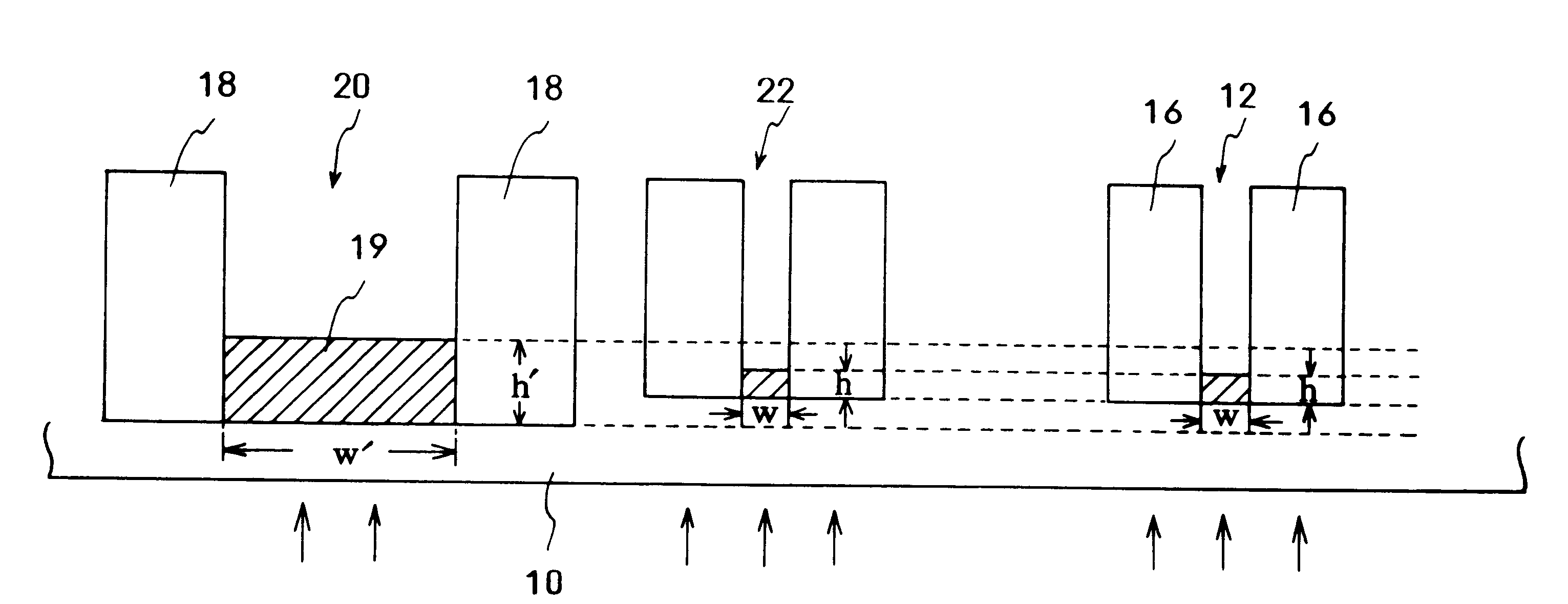
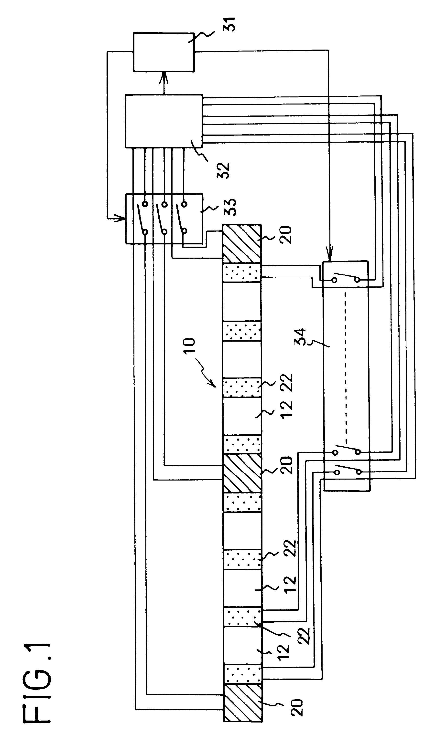
FIG. 1 briefly shows a structure of an example of a bar-shaped member 10 in which magnetic head elements 12 including sensing sections of magnetic resistance elements, first ELG elements 20 and second ELG elements 22 are formed. A shape of each first ELG element 20 is similar to that of the conventional ELG element, which is used to detect amount of lapping the bar-shaped member 10. The first ELG elements 20 are mainly used as monitor elements so as to precisely control sizes of the magnetic head elements 12. If the bar-shaped member 10 is deformed, the amount of lapping is partially different, so a plurality of- the first ELG members 20 are provided at both ends and a center of the bar-shaped member 10, with prescribed separations, so as to detect the deformation thereof.

Each second ELG element 22 is located at a mid portion between the adjacent magnetic head elements 12. Since the bar...


PUM

PropertyMeasurementUnit
thicknessaaaaaaaaaa
heightaaaaaaaaaa
widthaaaaaaaaaa

Abstract

The method of manufacturing a magnetic head comprises the steps of: forming a plurality of layers, which are made from prescribed materials, on a substrate; and forming a plurality of magnetic head elements 12 on the substrate. Using a first ELG element 20, whose size in a prescribed direction is bigger than that of the magnetic head elements 12, and a second ELG element 22, whose size is equal to that of the magnetic head elements, on the substrate, a work piece is lapped, while monitoring resistance of the first ELG element 20 when the resistance of the first ELG element 20 reaches a prescribed value, the amount of lapping the work piece is adjusted on the basis of resistance of the second ELG element 22. Thus, a bar-shaped member can be precisely lapped, the magnetic heads can be manufactured without scattering their characteristics, and yield rate of manufacturing can be improved.

Description

FIELD OF TECHNOLOGYThe present invention relates to a method of manufacturing a magnetic head for a magnetic disk drive unit, etc., and more precisely to a method of manufacturing a magnetic head in which a side face of a ceramic bar member, which includes magnetic head elements, is lapped so as to make the magnetic head elements have prescribed characteristics.BACKGROUND TECHNOLOGYMagnetic head elements used in magnetic disk drive units, etc. have sensing sections, which are formed by forming magnetic layers, non-magnetic layers, etc. on a wafer-shaped ceramic substrate, and terminals connected thereto. Sliders, which will be respectively assembled in magnetic heads and each of which includes a magnetic head element, are formed by dividing the wafer into pieces.The magnetic head elements are formed by the steps of forming the sensing sections and terminals in the substrate dividing the wafer into thin bar-shaped members 10 (see FIG. 4); and lapping a side face of the bar-shaped mem...

Claims


Application Information

Patent Timeline
Patent Type & Authority Patents(United States)
IPC IPC(8): G11B5/31G11B5/39G11B5/127
CPCG11B5/3166G11B5/3173G11B5/3903G11B5/3116Y10T29/49048Y10T29/49041Y10T29/49032Y10T29/49036
Inventor WATANUKI, MOTOICHI
Owner FUJITSU LTD
Why Eureka
Try Eureka