Electron source

a technology of electrostatic control and cathode, which is applied in the manufacture of electrode systems, electrode discharge tubes/lamps, and tubes with electrostatic controls, etc., can solve the problems of gas degrading the measurement environment, requiring time for cathode desorbed gasses from the cathode surface, and affecting the measurement effect of the cathode surface, etc., to achieve the effect of simple and efficient, inexpensive and simpl

Inactive Publication Date: 2003-03-18
MICROWAVE POWER TECH
View PDF12 Cites 25 Cited by
  • Summary
  • Abstract
  • Description
  • Claims
  • Application Information

AI Technical Summary

Benefits of technology

It is another object of the present invention to provide an inexpensive, simple and efficient electron source.

Problems solved by technology

The heating of the cathode requires time and causes gasses to be desorbed from the cathode surface.
These gases degrade the measurement environment, particularly in vacuum gauges.
However, such emitters are costly due to the multiple lithographic processes required to produce them.
In addition, they have limited operational life when operated at pressures higher than 10.sup.-6 Torr.

Method used


Image

  • Electron source
  • Electron source
  • Electron source

Examples


Embodiment Construction

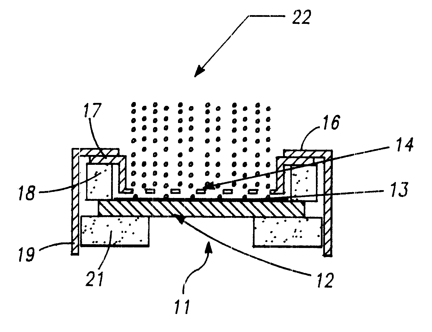
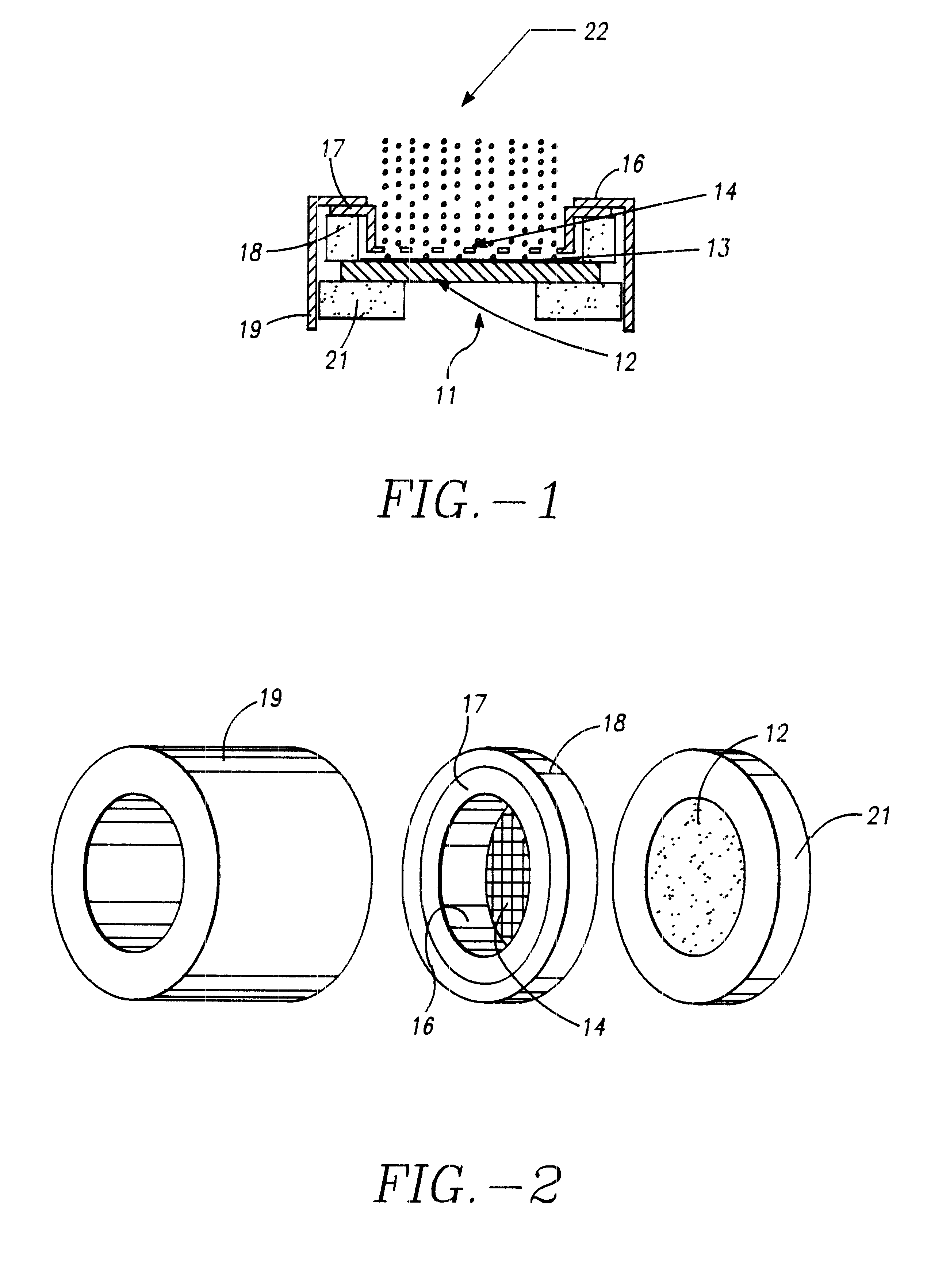
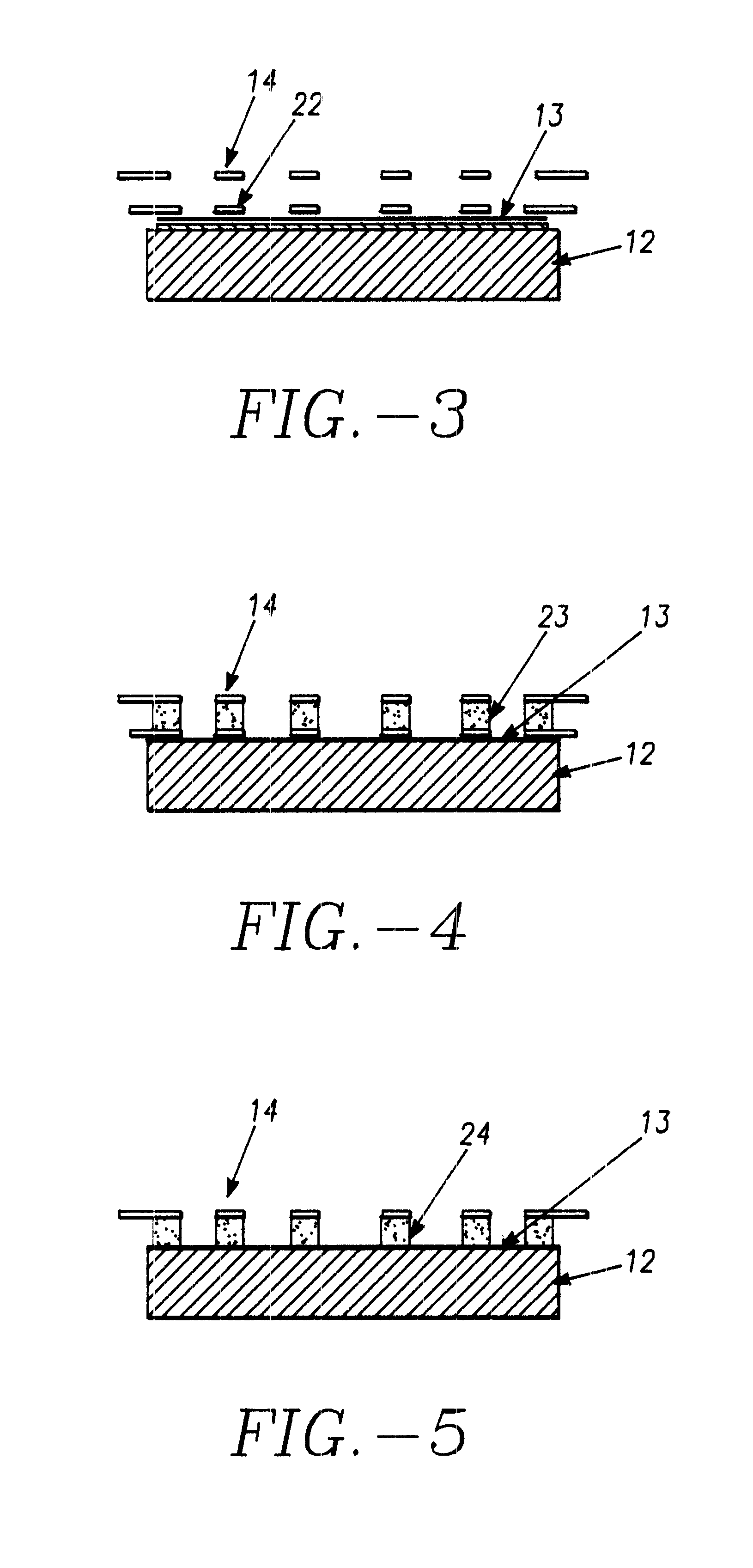
The electron source includes a cold electron emitter or cathode 11, FIG. 1. The cold cathode emitter includes a metal, ceramic or semiconductor substrate 12 onto which is formed and electron emitting film 13. The film comprises nanostructured carbon which may be formed as disclosed in the patents and articles referred to above. The emitter film is deposited on an area tailored in shape and size to produce sufficient current and electron beam cross-section suited to specific applications when a voltage is applied between the electron extraction grid 14 and the closely-spaced surface of the film 13. The magnitude of the emitted current is controlled by the magnitude of the voltage or potential. The close spacing assures that electric fields above the threshold value can be achieved with low voltages applied to the grid. The electron extraction grid 14 is carried at the bottom of a cup shaped electrode or frame 16 which has a rim 17. The spacing between the extraction grid and the film...


PUM


Abstract

An electron source including a nanostructured carbon electron-emitting film and an electron extraction grid spaced closely adjacent the surface of said film.

Description

This invention relates generally to an electron source and more particularly to a cold electron source for supplying electrons which can collide with gas molecules to form ions or ion species in vacuum gauges and analytical instruments.Electron emitters used in electron sources are primarily hot filaments which must be operated at temperatures ranging from 1000 to 2200 degrees Celsius. The heating of the cathode requires time and causes gasses to be desorbed from the cathode surface. These gases degrade the measurement environment, particularly in vacuum gauges.Electron sources using cold emission emitters are known. The electron emission mechanism is electric field assisted tunneling at the surface (field emission) which has the characteristic that the density of the emitted current is determined solely by the electric field at the emitter surface. Since the emitted current is independent of temperature, the full current capacity of the emitter is available at or below room tempera...

Claims


Application Information

Patent Timeline
Patent Type & Authority Patents(United States)
IPC IPC(8): H01J3/02H01J3/00
CPCB82Y10/00H01J3/021Y10S977/939H01J2201/30469
Inventor ESPINOSA, ROBERT J.
Owner MICROWAVE POWER TECH
Why Eureka
Try Eureka