Piezoelectric ink jet printer head and method for manufacturing same

a technology of ink jet printers and ink jets, applied in printing and other directions, can solve the problems of increasing production costs, and achieve the effect of increasing production costs and high positive pressur

Inactive Publication Date: 2003-03-25
BROTHER KOGYO KK
View PDF9 Cites 15 Cited by
  • Summary
  • Abstract
  • Description
  • Claims
  • Application Information

AI Technical Summary

Benefits of technology

However, because the lowermost piezoelectric ceramic layer 140 is inactive in this way, a sufficiently high positive pressure is not generated in the ink chambers 131. It is conceivable to screen print another electrode for driving the lowermost piezoelectric ceramic layers 140 onto the surface where the lowermost ceramic layer 140 attaches to the cavity plate 130. However, a separate insulation film would need to be formed on this electrode to protect it from the ink in the ink chambers 131. This extra film would increase production costs.

Problems solved by technology

This extra film would increase production costs.

Method used


Image

  • Piezoelectric ink jet printer head and method for manufacturing same
  • Piezoelectric ink jet printer head and method for manufacturing same
  • Piezoelectric ink jet printer head and method for manufacturing same

Examples


Embodiment Construction

Next, an ink jet printer head with a configuration, and produced by a method, according to the present invention will be described while referring to the attached drawings.

It should be noted that the following explanation of the embodiment will be easier to understand by referring to U.S patent application Ser. Nos. 09 / 897,394; 09 / 933,155; 09 / 933,156; and U.S Patent Application titled LAMINATED AND BONDED CONSTRUCTION OF THIN PLATE PARTS filed with the U.S. Patent and Trademark Office on Sep. 21, 2001, the disclosure of all of which is incorporated herein by reference in their entirety.

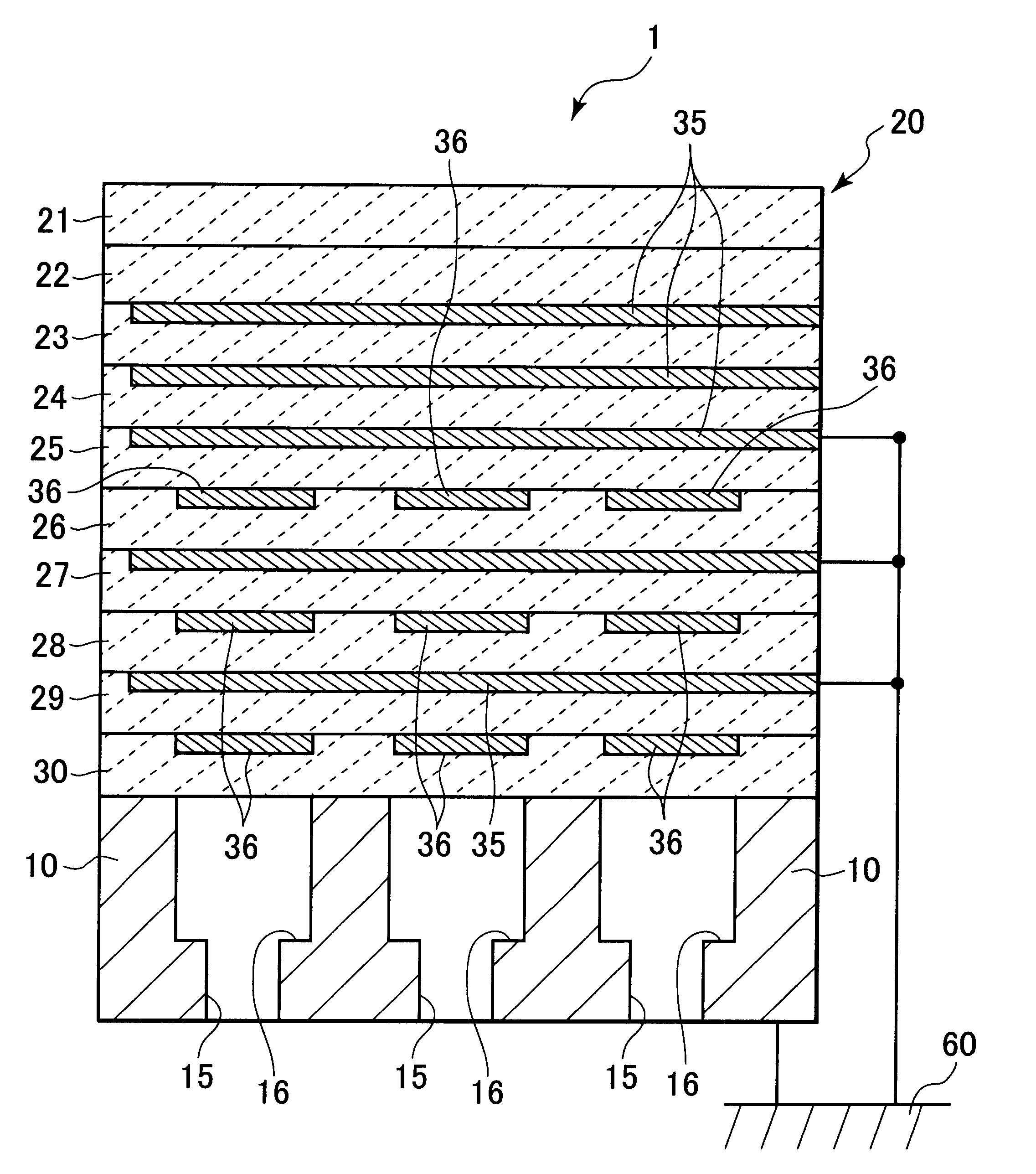
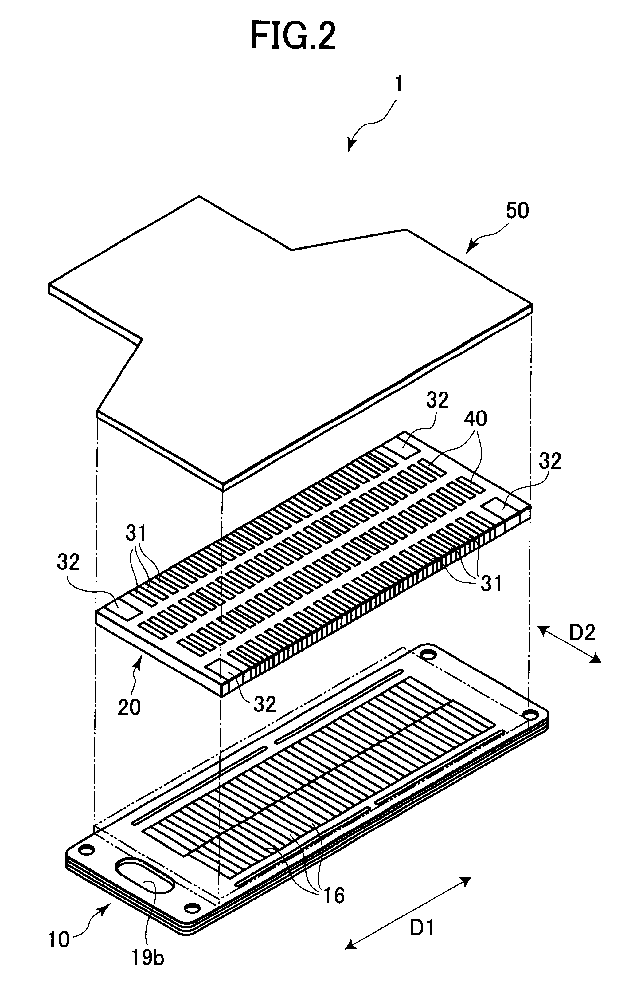
As shown in FIG. 2, an ink jet printer head 1 includes a cavity plate 10, a plate-shaped actuator 20, and a flexible flat cable 50. The cavity plate 10 has a laminated configuration formed from a plurality of approximately rectangular conductive metal plates. Pressure chambers 16 are formed by grooves in the surface of the cavity plate 10. The pressure chambers 16 are aligned in parallel with the leng...


PUM


Abstract

A plate-shaped piezoelectric actuator 20 is formed from ten piezoelectric sheets 21 to 30 that are stacked in a laminated configuration. Drive electrodes 36 are formed on the upper surface of each piezoelectric sheet 26, 28, and 30 at positions that correspond to pressure chambers 16 provided on a cavity plate 10. A band-shaped common electrode 35 is formed on the surface of each of the piezoelectric sheets 23, 24, 25, 27, and 29. The piezoelectric sheets 25 to 30 are subjected to polarization processes by applying a voltage between the common electrodes 35 and corresponding ones of the drive electrodes 36 and between the drive electrode 36 of the lowermost piezoelectric sheet 30 and the cavity plate 10. Then, the common electrodes 35 provided on the piezoelectric sheets 25, 27, 29 and the cavity plate 10 are all connected to the ground 60. With this configuration, the piezoelectric sheet 30 as well as the piezoelectric sheets 26 to 29 function as active layers and deform by the piezoelectric effect.

Description

BACKGROUND OF THE INVENTION1. Field of the InventionThe present invention relates to a piezoelectric ink jet printer head and a method for manufacturing the same.2. Description of the Related ArtFIG. 1 shows a conventional ink jet printer head 100 used in an ink jet printer. The ink jet printer head 100 includes a cavity plate 130 and a piezoelectric actuator 110. The cavity plate 130 is formed with a plurality of ink chambers 131. The piezoelectric actuator 110 is adhered onto the cavity plate 130 so as to cover the ink chambers 131. When a voltage is applied to the piezoelectric actuator 110, the piezoelectric actuator 110 deforms into the ink chambers 131, whereupon the volume of the ink chambers 131 decreases. As a result, the pressure in the ink chambers 131 increases so that an ink droplet is ejected from the orifices 132 of the ink chambers 131.The piezoelectric actuator 110 includes active layers 120 and inactive binding layers 150. The active layers 120 include piezoelectri...

Claims


Application Information

Patent Timeline
Patent Type & Authority Patents(United States)
IPC IPC(8): B41J2/14B41J2/16B41J2/055B41J2/045
CPCB41J2/14209B41J2/1609B41J2/1623B41J2002/14225B41J2002/14217
Inventor TAKAGI, ATSUHIRO
Owner BROTHER KOGYO KK
Why Eureka
Try Eureka