Straightly-inserted terminal with low inserting force and high extracting force

A technology of in-line terminals and low insertion force, which is applied in the field of terminal blocks and in-line terminals, can solve the problems of stable connection with small insertion resistance, and achieve the effects of easy insertion, stable connection, and large operating range

Active Publication Date: 2012-11-21
浙江珠城科技股份有限公司
View PDF7 Cites 7 Cited by
  • Summary
  • Abstract
  • Description
  • Claims
  • Application Information

AI Technical Summary

Problems solved by technology

[0004] The technical problem to be solved by the present invention is that the female terminal of the in-line terminal in the prior art cannot simultaneously

Method used


Image

  • Straightly-inserted terminal with low inserting force and high extracting force
  • Straightly-inserted terminal with low inserting force and high extracting force
  • Straightly-inserted terminal with low inserting force and high extracting force

Examples


Embodiment 1

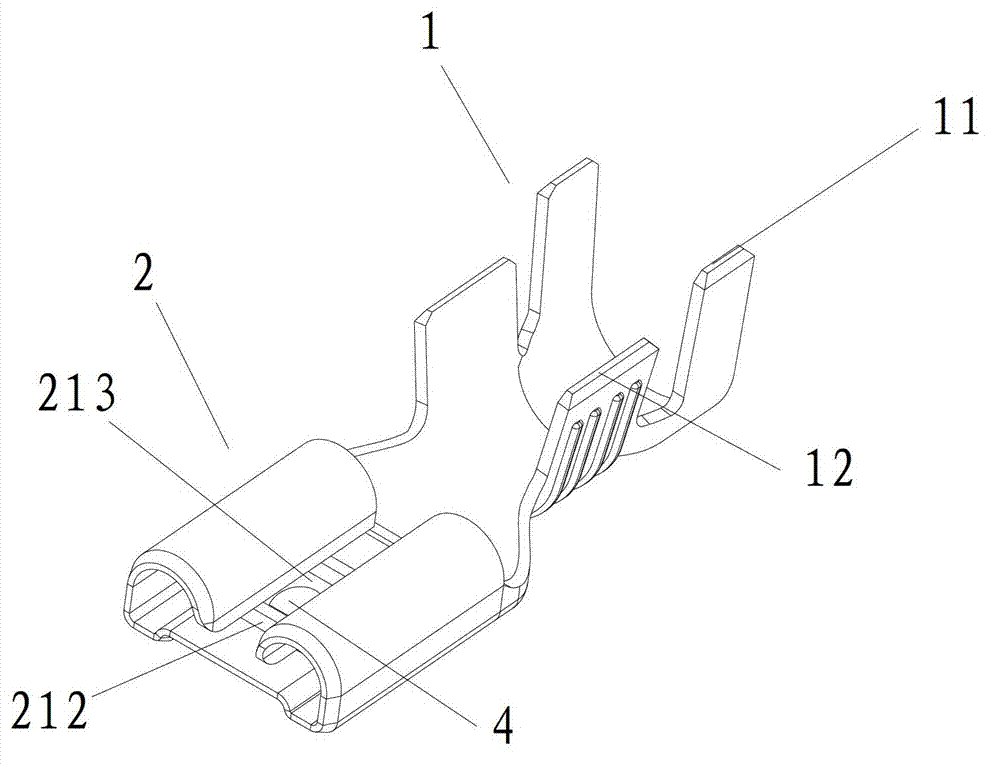
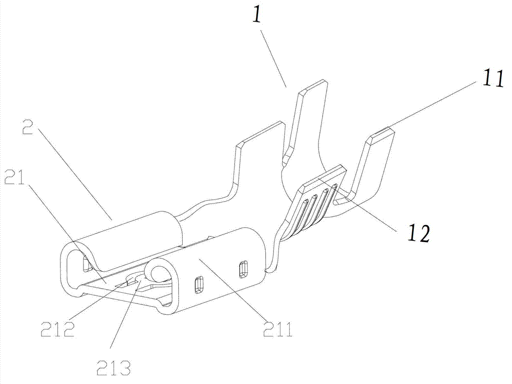
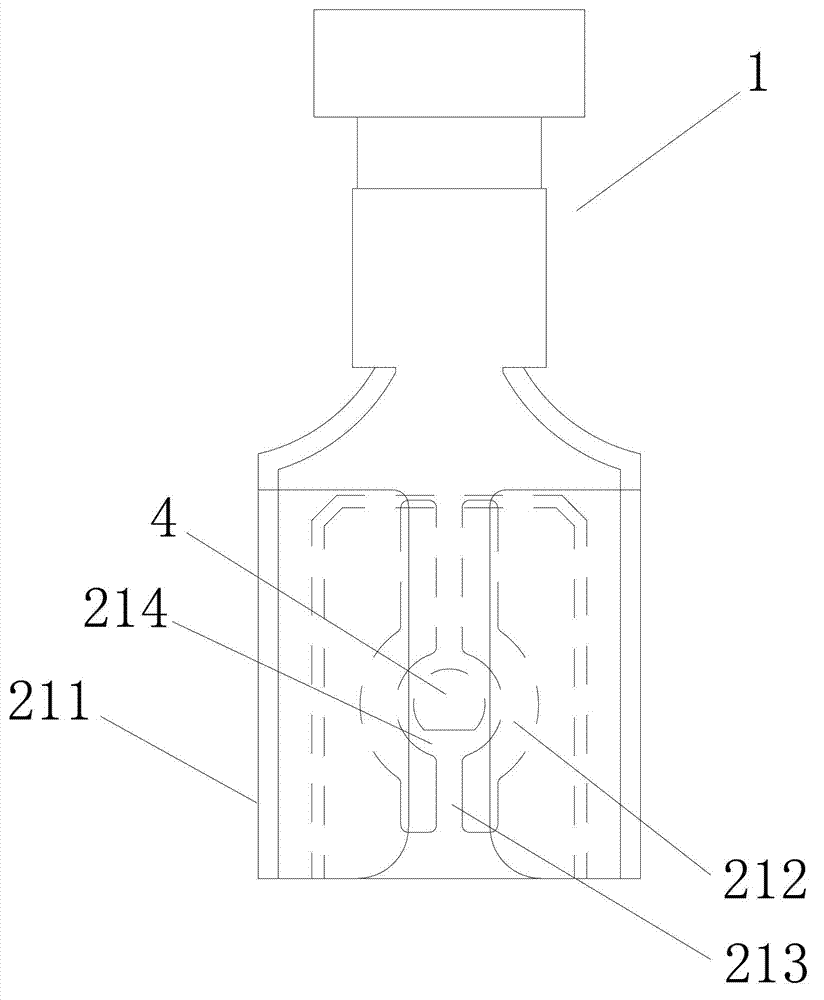
[0029] The structure of the in-line terminal described in the present invention is shown in figure 2 As shown, it includes a cable connection part 1 and a female terminal 2 connected in a straight line. The cable connecting part 1 is used for connecting cables, and generally includes a covering part 11 for wrapping the cable and a pressing part 12 for pressing the cable core. The female connection terminal 2 is used to connect a male connection terminal, such as a plug-in piece. The female terminal 2 includes a slot 21, the two sides of the slot 21 are arc-shaped tubular sidewalls 211, and the bottom of the slot 21 is formed with two slits 212, where the slits are arranged longitudinally, such as image 3 As shown, the width of the gap is set to 0.25mm. An elastic arm 213 is formed between the two slits 212, the length of the elastic arm 213 is 6 mm, and the width at both ends is 0.9 mm. The middle part of the elastic arm 213 is formed with a central expansion part 214, se...

Embodiment 2

[0032] On the basis of the in-line terminal described in the above embodiments, the inner wall of the arc-shaped tubular side wall 211 of the slot 21 may also be formed with a limited protrusion. The central expansion part 214 is provided with a locking protrusion 4, and the height of the locking protrusion 4 increases from one end close to the notch of the slot 21 to the other end, see image 3 .Such a structure has a smooth transition when inserting the male terminal, which is easy to insert, and has a groove structure when pulling out, so it is not easy to pull out, making the effect of low insertion force and high pull-out force more obvious. Further, on the bottom of the slot 21 and one end away from the notch of the slot 21, on the outside of the elastic arm 213, a blocking protrusion can also be provided, and the blocking protrusion can limit the connection of the male terminal. into depth.

[0033] The width of the elastic arm 213 of the in-line terminal in the prior ar...


PUM

PropertyMeasurementUnit
Lengthaaaaaaaaaa
Lengthaaaaaaaaaa
Widthaaaaaaaaaa

Abstract

The invention relates to a straightly-inserted terminal with a low inserting force and a high extracting force. The straightly-inserted terminal comprises a cable connecting part and a wiring female terminal which are linearly connected, wherein the wiring female terminal comprises a slot; arc tubular side walls are arranged on two sides of the slot; two clearances are formed in the bottom of the slot and an elastic arm is formed between the two clearances; a central expanding part is formed in the middle of the elastic arm; and the width of the central expanding part is greater than the widths of two ends of the elastic arm. Due to the arrangement of the central expanding part, the stress area is increased when a male wiring terminal is connected, further a greater elasticity for the elastic arm can be generated and the elasticity is enabled to exert the action during inserting and the male wiring terminal is easily inserted; and in addition, after being inserted, the male wiring terminal can be stably connected and is extracted by using greater effort.

Description

technical field [0001] The invention relates to a connection terminal, in particular to an in-line terminal with low insertion force and high extraction force, and belongs to the technical field of connection components and connectors. Background technique [0002] Terminal block is an accessory product used to realize electrical connection. It belongs to the category of connectors in industry and is widely used in electronic and electrical fields, such as ballasts, transformers, switching power supplies, instruments and meters, IT communications, alarm devices, and elevator equipment. , lighting, household appliances, etc. With the increasing degree of industrial automation and the increasingly strict and precise industrial requirements, higher requirements are put forward for the wiring flexibility and connection reliability of the terminal blocks. [0003] figure 1 An in-line terminal in the prior art is provided, which is mainly used in electrical equipment such as hou...

Claims


Application Information

Patent Timeline
IPC IPC(8): H01R11/11H01R4/48
Inventor 龙云付
Owner 浙江珠城科技股份有限公司
Why Eureka
Try Eureka