Improved connecting rod drive mechanism of butterfly valve plate

A technology of connecting rod drive and butterfly valve plate, applied in the direction of valve housing structure, engine components, lift valve, etc., can solve the problems of high power input requirements of supporting power source, structural deformation limitation, and difficulty in guaranteeing the reverse sealing effect of the sealing pair, etc.

Active Publication Date: 2017-08-11
SHITSZJACHZHUAN SANKHUAN VEHLV KORPOREHJSHEN
View PDF9 Cites 6 Cited by
  • Summary
  • Abstract
  • Description
  • Claims
  • Application Information

AI Technical Summary

Problems solved by technology

[0007]First, the driving power is limited and the supporting power source is required to be high. Because it adopts a single driving method for the valve stem, the valve plate can be sealed under the premise of ensuring the sealing effect. The stress applied on the valve is limited. Since the driving force of the valve plate is input through the valve stem, the power input requirements for the supporting power source are high, and the structural deformation of the valve stem and other transmission components is limited by the input power.
The second is that in practical applications, due to the reverse air wave impact of the sealing pair, resonance in the medium transmission process, etc., it is easy to cause the problem that the reverse sealing

Method used


Image

  • Improved connecting rod drive mechanism of butterfly valve plate
  • Improved connecting rod drive mechanism of butterfly valve plate

Examples


Embodiment

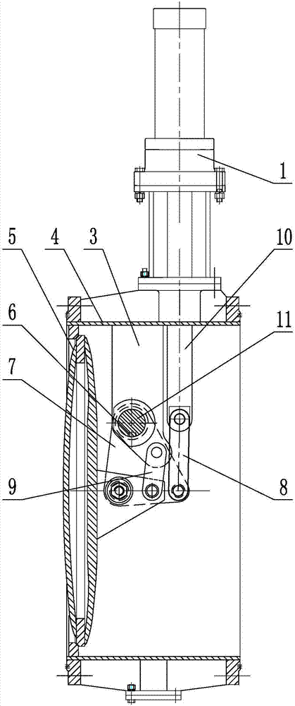
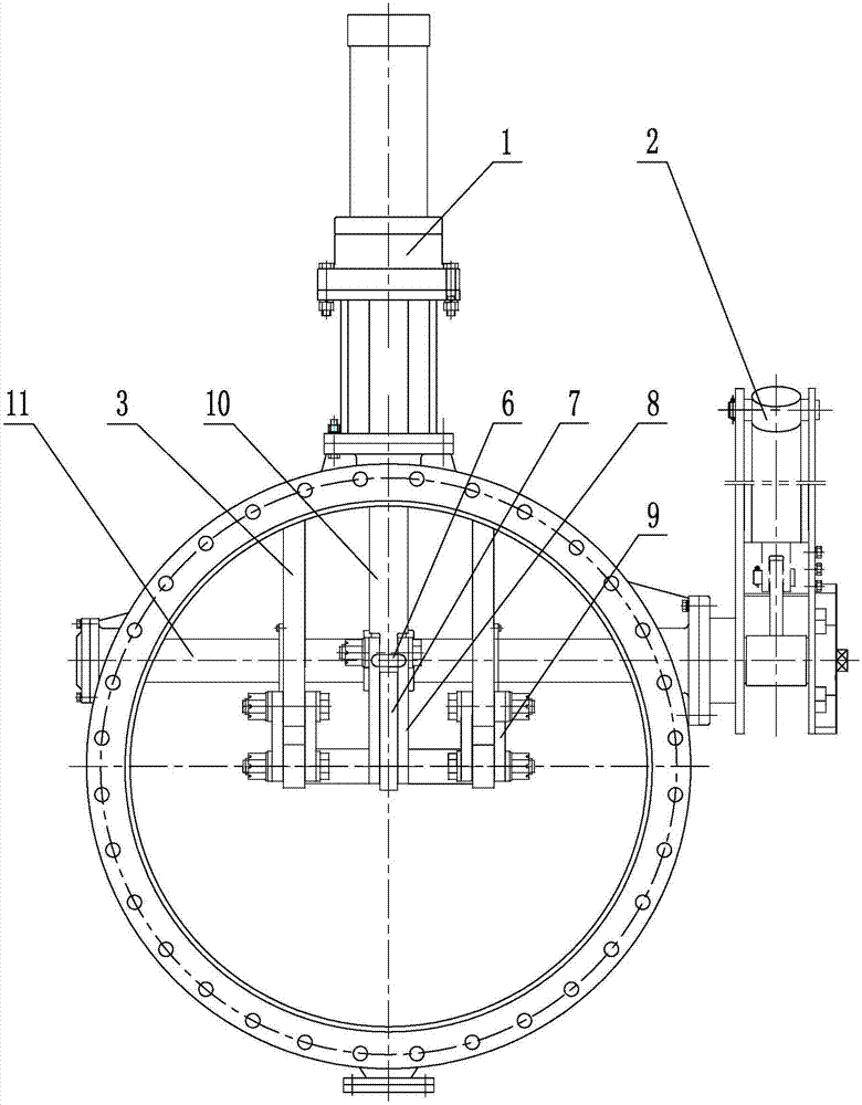
[0081] The improved connecting rod drive mechanism of the butterfly valve plate includes a valve body 4, a valve plate 5, a push-pull drive shaft 10 located in the valve body 4 and driven longitudinally by the parallel push-pull mechanism 1, the valve plate 5 is located in the valve body 4, and the triangular plate 7 It is perpendicular to the valve plate 5 and the main shaft 11 and its top is matched with the main shaft 11. The lower inner end of the triangular plate 7 is hinged with the fixed seat on the valve plate 5, and the lower outer end of the triangular plate 7 is movably assembled with the lower end of the push-pull drive shaft 10. The valve plate 5. The triangular plate 7 is driven by the push-pull drive shaft 10 to achieve sealing and locking or separation from the medium delivery channel opened in the valve body 4; Drive and rotate synchronously with the radial direction of the triangular plate 7.

[0082] The outer side of the valve plate 5 is provided with a rig...


PUM


Abstract

The invention belongs to butterfly valve components and particularly relates to an improved connecting rod drive mechanism of a butterfly valve plate. The improved connecting rod drive mechanism comprises a valve body, a valve plate and a push-pull drive shaft which is located in the valve body and longitudinally driven by a parallel push-pull mechanism. The valve plate is located in the valve body, a triangular plate is perpendicular to the valve plate and a main shaft, the top end of the triangular plate is connected with the main shaft in a matched manner, the inner end of the lower portion of the triangular plate is hinged to a fixing base on the valve plate, the outer end of the lower portion of the triangular plate and the lower end of the push-pull drive shaft are movably assembled, and the valve plate achieves sealed locking or separating in a manner that the push-pull drive shaft drives the triangular plate and a medium conveying channel formed in the valve body. The two ends of the main shaft are in rotation fit with the inner wall of the valve body, the main shaft is driven by a rotary drive mechanism, and the main shaft and the triangular plate synchronously rotate in the radial direction. The improved connecting rod drive mechanism effectively solves the technical problem that in the prior art, the reverse sealing effect is poor due to single drive. The improved connecting rod drive mechanism has the beneficial effects that bi-drive can effectively increase force, and a certain reverse sealing property is achieved while the forward sealing effect is guaranteed.

Description

technical field [0001] The invention belongs to a butterfly valve component, in particular to an improved connecting rod driving mechanism of a butterfly valve plate. Background technique [0002] As an important part of the equipment manufacturing industry, the valve industry plays a very important role in the development of the national economy. There are many valve industry chains in China, but it is not a valve powerhouse. Generally speaking, my country has entered the ranks of the world's valve powers, but there is still a certain gap between my country and the valve power in terms of product quality. The industry's low production concentration, low R&D capabilities for high-end valves, and low manufacturing technology in the valve industry still exist. Many high-parameter, high-temperature, high-pressure, and high-pound key valves have always relied on imports. In order to promote the localization of valves, after the "Several Opinions on Accelerating the Revitalizati...

Claims


Application Information

Patent Timeline
IPC IPC(8): F16K1/22F16K1/226F16K1/46F16K27/02F16K31/44
CPCF16K1/221F16K1/2261F16K27/0218F16K31/44
Inventor 魏明义张彦腾张福刚贾占良
Owner SHITSZJACHZHUAN SANKHUAN VEHLV KORPOREHJSHEN
Why Eureka
Try Eureka