Apparatus and method for recording an optical disc identification code
- Summary
- Abstract
- Description
- Claims
- Application Information
AI Technical Summary
Benefits of technology
Problems solved by technology
Method used
Image
Examples
first embodiment
(1-3) Effect of First Embodiment
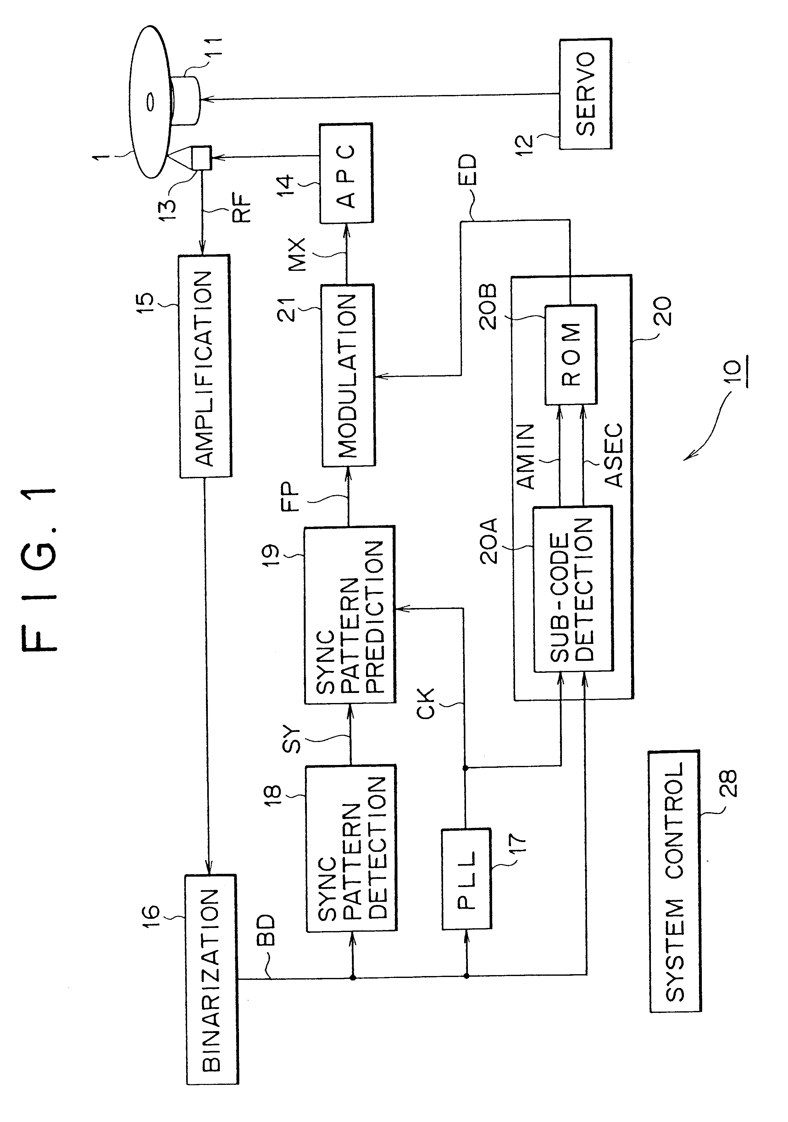
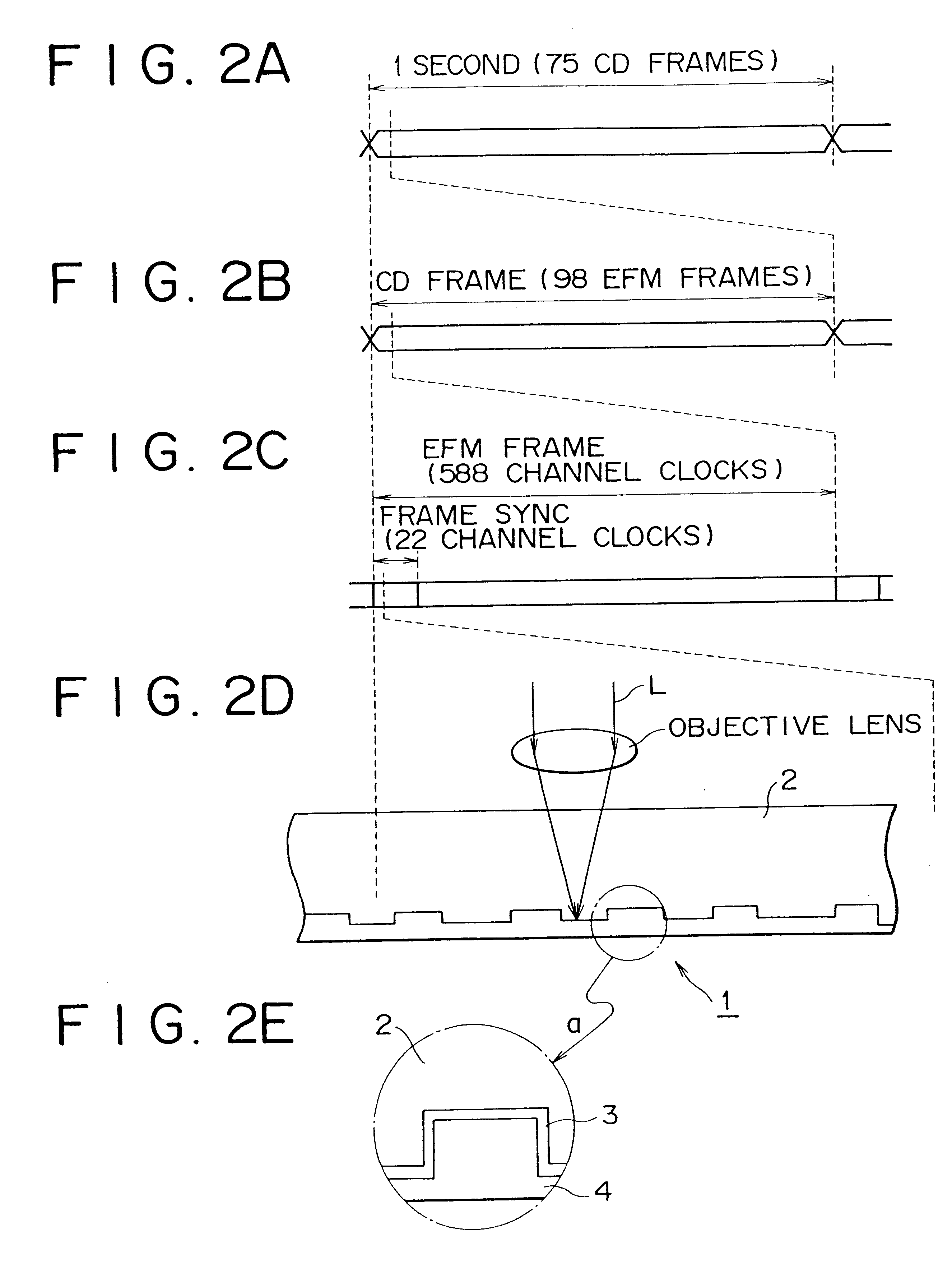
According to the above-mentioned structure, the pit and land of the sync pattern having 11T cycles is detected, the mark is formed at the middle of the pit and land which is located a distance corresponding to a value equal to or larger than 4T cycles apart from the edge and the disc identification code is recorded, the reflection film of the pit and land is locally changed at the timing so as not to adversely affect the position information of the edge, as the result the disc identification code is recorded so that the disc identification code does not cause any adverse effect on reproduction of the digital audio signal D1 in the form of pit string, and the disc identification code is reproduced by the optical pickup for reproducing the digital audio signal D1 and is difficult to be illegally copied.
The disc identification code is recorded by marking on the pit and land of the sync pattern recorded periodically, and the disc identification code can b...
second embodiment
(2) SECOND EMBODIMENT
FIG. 7 is a block diagram for illustrating a finishing unit in accordance with the second embodiment of the present invention. The finishing unit 60 detects pits having a cycle equal to or longer than 9T, and records the disc identification code ED on these pits. In the structure shown in FIG. 7, the same components as those of the finishing unit 10 shown in FIG. 1 are given the same corresponding characters, and the repeated description is omitted.
In detail, in the finishing unit 60, the system control circuit 61 comprises a computer for controlling the whole operation of the finishing unit 60, controls the operation of an optical pickup 13 with reference to a sub-code detected from the reproduction signal RF, and traces successively twice the area set on the recording area of the disc identification code ED by means of the optical pickup 13.
At that time, the system control circuit 61 holds the trace signal T1 in logic 0 in the first trace, on the other hand, s...
third embodiment
(3) THIRD EMBODIMENT
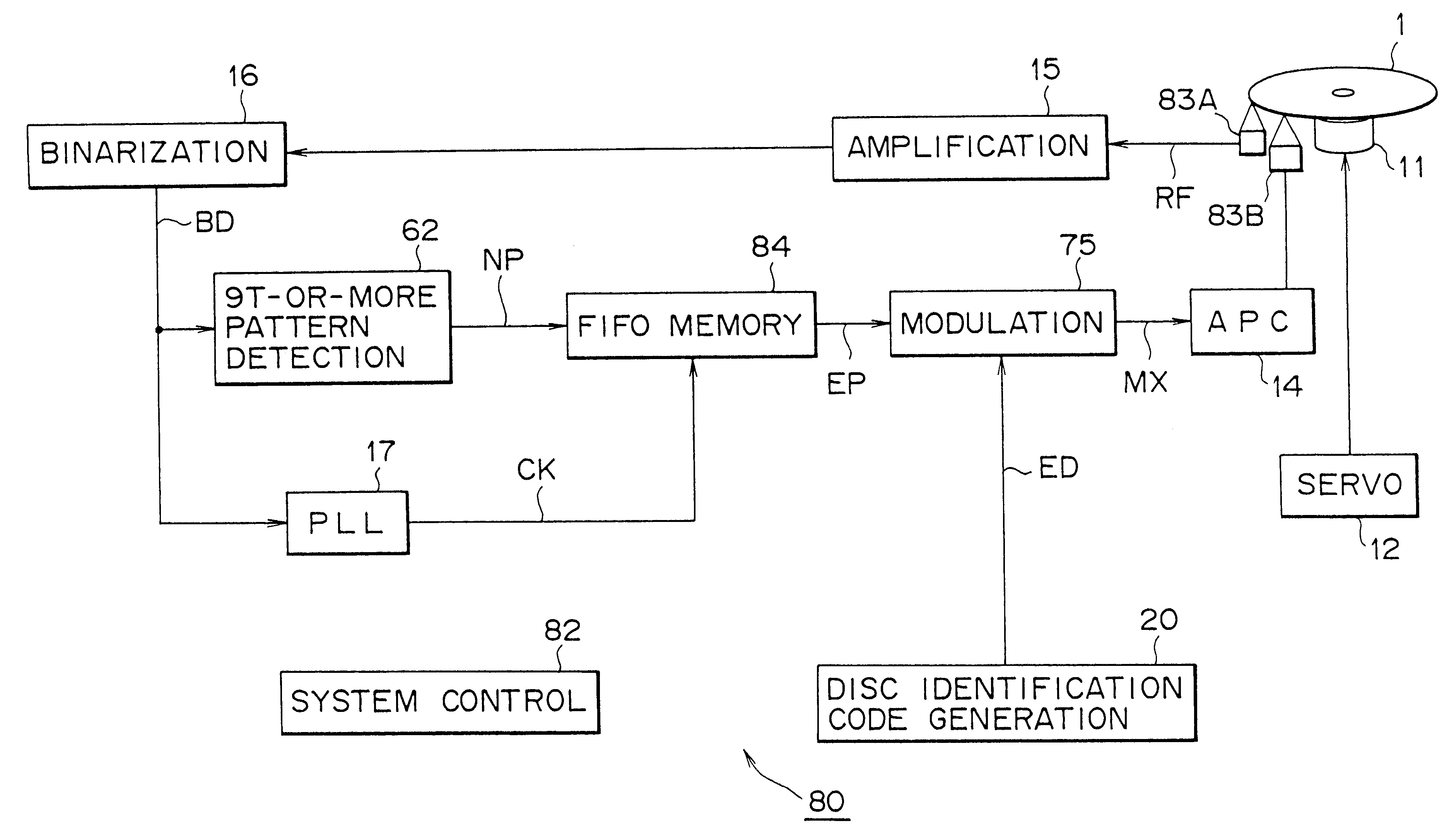
FIG. 10 is a block diagram for illustrating a compact disc 1 finishing unit in accordance with the third embodiment. This finishing unit 80 performs pit detection processing of the pit having a length equal to or longer than 9T cycles and additional recording processing of the disc identification code simultaneously in parallel. The same components shown in the structure shown in FIG. 10 as those of the above-mentioned finishing unit 60 shown in FIG. 7 are given the same corresponding characters, and repeated description is omitted.
In detail, in the present embodiment, the finishing unit 80 is provided with a preceding read out optical pickup 83A and a recording optical pickup 83B for scanning the scanned trace where the preceding read out optical pickup 83A has scanned with a delay of a predetermined time period.
The finishing unit 80 processes the reproduction signal RF suplied from the preceding read out optical pickup 83A to detect the pit having a length equa...
PUM
| Property | Measurement | Unit |
|---|---|---|
| time | aaaaa | aaaaa |
| time | aaaaa | aaaaa |
| wavelength | aaaaa | aaaaa |
Abstract
Description
Claims
Application Information
 - R&D
- Intellectual Property
- Life Sciences
- Materials
- Tech Scout
- Unparalleled Data Quality
- Higher Quality Content
- 60% Fewer Hallucinations
Browse by: Latest US Patents, China's latest patents, Technical Efficacy Thesaurus, Application Domain, Technology Topic, Popular Technical Reports.
© 2025 PatSnap. All rights reserved.Legal|Privacy policy|Modern Slavery Act Transparency Statement|Sitemap|About US| Contact US: help@patsnap.com


