Billing system

a billing system and system technology, applied in the field of billing systems, can solve the problems of time-consuming and laborious modification of these services and the introduction of new services

Inactive Publication Date: 2003-03-25
BRITISH TELECOMM PLC
View PDF9 Cites 338 Cited by
  • Summary
  • Abstract
  • Description
  • Claims
  • Application Information

AI Technical Summary

Problems solved by technology

This means that the modification of these services an

Method used


Image

  • Billing system
  • Billing system
  • Billing system

Examples


Embodiment Construction

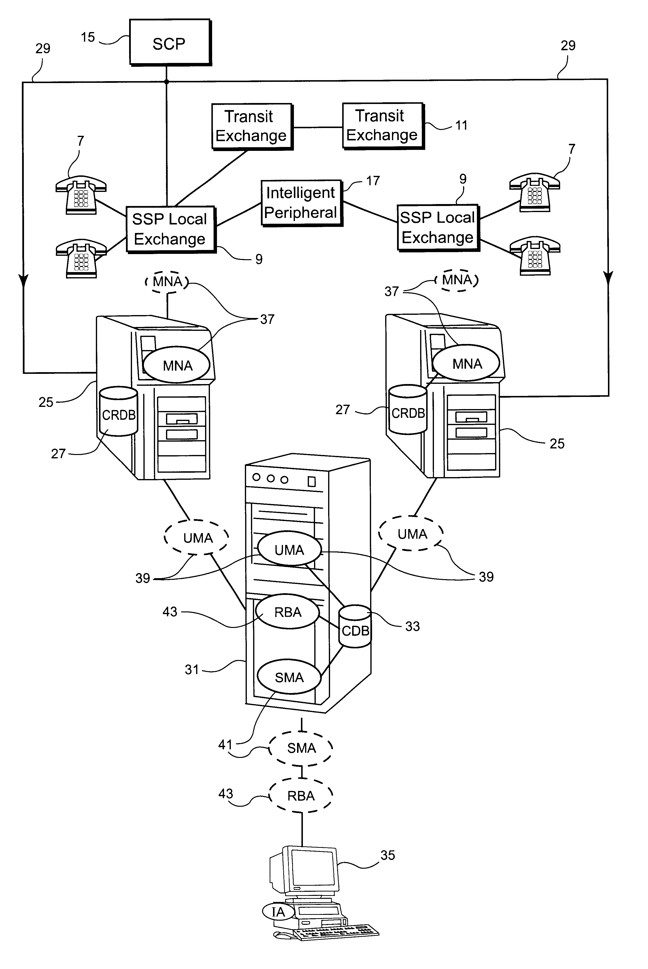
FIG. 4 shows an intelligent telecommunications network that has a plurality of telephones (7) connected to two local exchanges / SSPs (9), each of which is connected to a service control point (SCP) (15). Typically, for example, the SCP (15) is a Siemens Nisxdorf RM600, with 8 CPU cards per half, with the SCP node made up of two halves. Each of the SSPs (9) is able to detect the occurrence of certain events over the whole duration of a call and report these to the SCP (15).

Associated with each SSP (9) is a switch side processor (25) that contains a local call record database (CRDB) (27) and is connected via a C7 link (29) to the SCP (15), the C7 protocol being part of the International standard SS7 signalling protocol. Connected to each of the switch side processors (25) is a central database server (31), in which is provided a central database (CDB) (33) for storing information from all the local call records databases (27). Connected to the central database server (31) is an intelli...


PUM


Abstract

A billing system for a telecommunications network uses a monitoring software agent to monitor messages, indicative of individual calls on the network, passing between a service switching point and a service control point. Call record information is extracted and is stored in a local call record database. Information from each call record database is then passed on to a central database, using updating mobile agents, the central database being accessible to such agents and report building agents which can extract billing information as requested by an operator. By monitoring the messages as they pass, the system can provide real time billing information without needing to poll the switch at the service switching point.

Description

1. Field of the InventionThis invention relates to a billing system. In particular, this invention relates to a billing system for billing customers to a telecommunications network.2. Description of Related ArtA known telecommunications network is shown in FIG. 1. This includes a plurality of telephones (7), each of which is connected to one of a plurality of local exchanges (9). Connected to the local exchanges (9) are transit exchanges (11) that are provided for routing calls between the local exchanges (9).On lifting a handset of one of the telephones (7) the user hears a dialling tone and dials the number of the person to be contacted. The dialled codes are decoded at the local exchange (9) and the call is routed to the appropriate destination. Any services such as call diversion, alarm-call, call waiting, etc are controlled by software that resides on the local exchanges (9). This means that the modification of these services and the introduction of new services are time-consum...

Claims


Application Information

Patent Timeline
IPC IPC(8): H04M15/00H04Q3/00
CPCH04M15/00H04M15/47H04M15/90H04Q3/0029H04M2215/016H04M2215/018H04M2215/0148
Inventor LOWE, COLINBUSUIOC, NICOLAE MARIUSDADGE, NIGEL GEOFFREY
Owner BRITISH TELECOMM PLC
Why Eureka
Try Eureka