Plug door drive system

a drive system and plug-in technology, applied in the direction of transportation and packaging, manufacturing tools, wing accessories, etc., can solve the problem of quite expensive planetary gear drives, and achieve the effect of simple pivoted link

Inactive Publication Date: 2003-04-01
WESTINGHOUSE AIR BRAKE TECH CORP
View PDF14 Cites 42 Cited by
  • Summary
  • Abstract
  • Description
  • Claims
  • Application Information

AI Technical Summary

Benefits of technology

It is an additional object of the present invention to provide a powered plug door for a vehicle which does not require the use of reaction torque on the motor.
Still yet another object of the present invention is to provide a plug door drive system in which outward and longitudinal movement is enabled by a linear drive mechanism and a simple pivoted link.

Problems solved by technology

It is noted that planetary gear drives are quite expensive.

Method used


Image

  • Plug door drive system
  • Plug door drive system
  • Plug door drive system

Examples


Embodiment Construction

, particularly, when the detailed description is taken in conjunction with the attached drawing figures and with the appended claims.

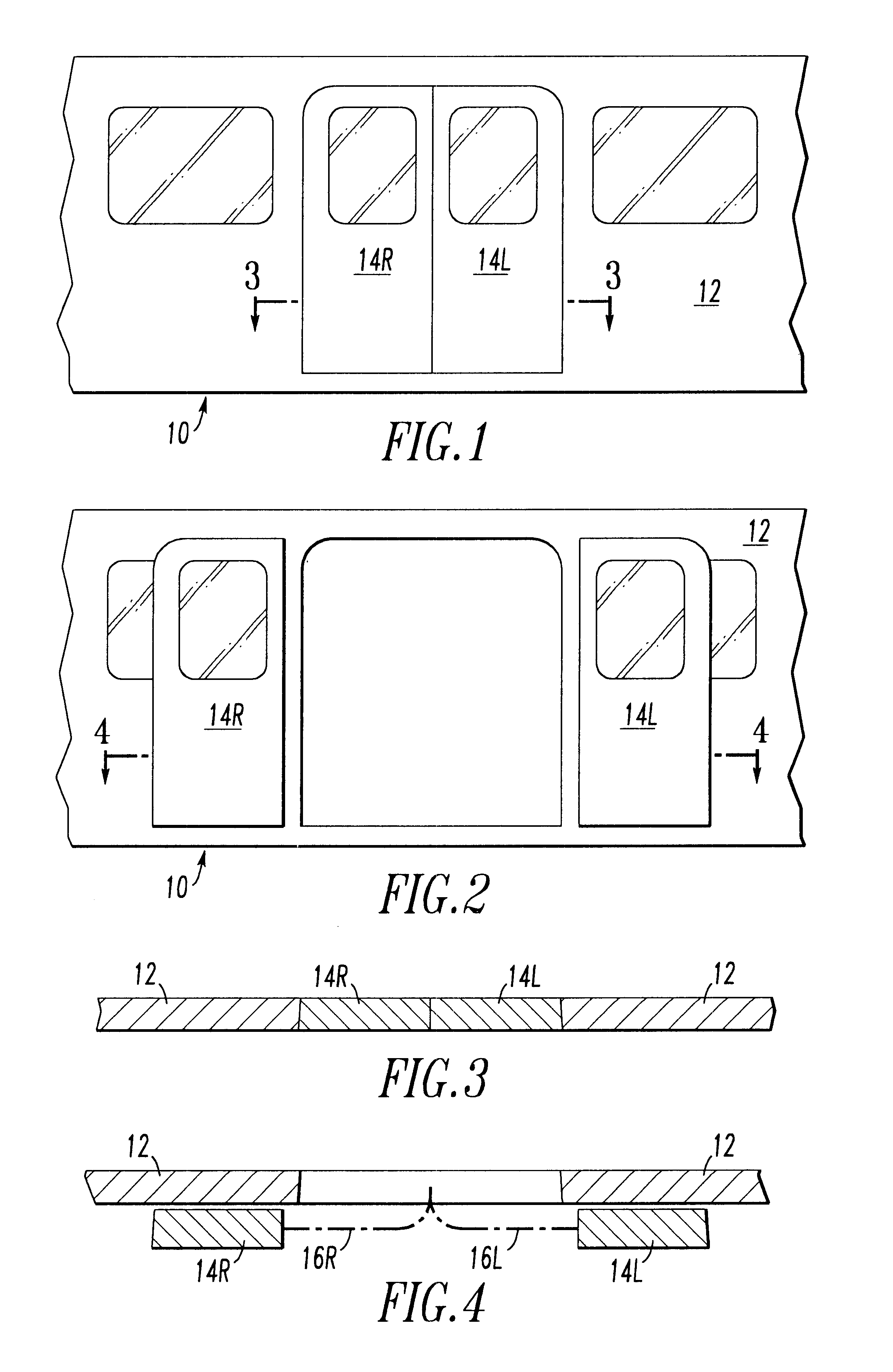
FIG. 1 is an elevation view from outside of a transit vehicle having plug doors which are in their closed positions.

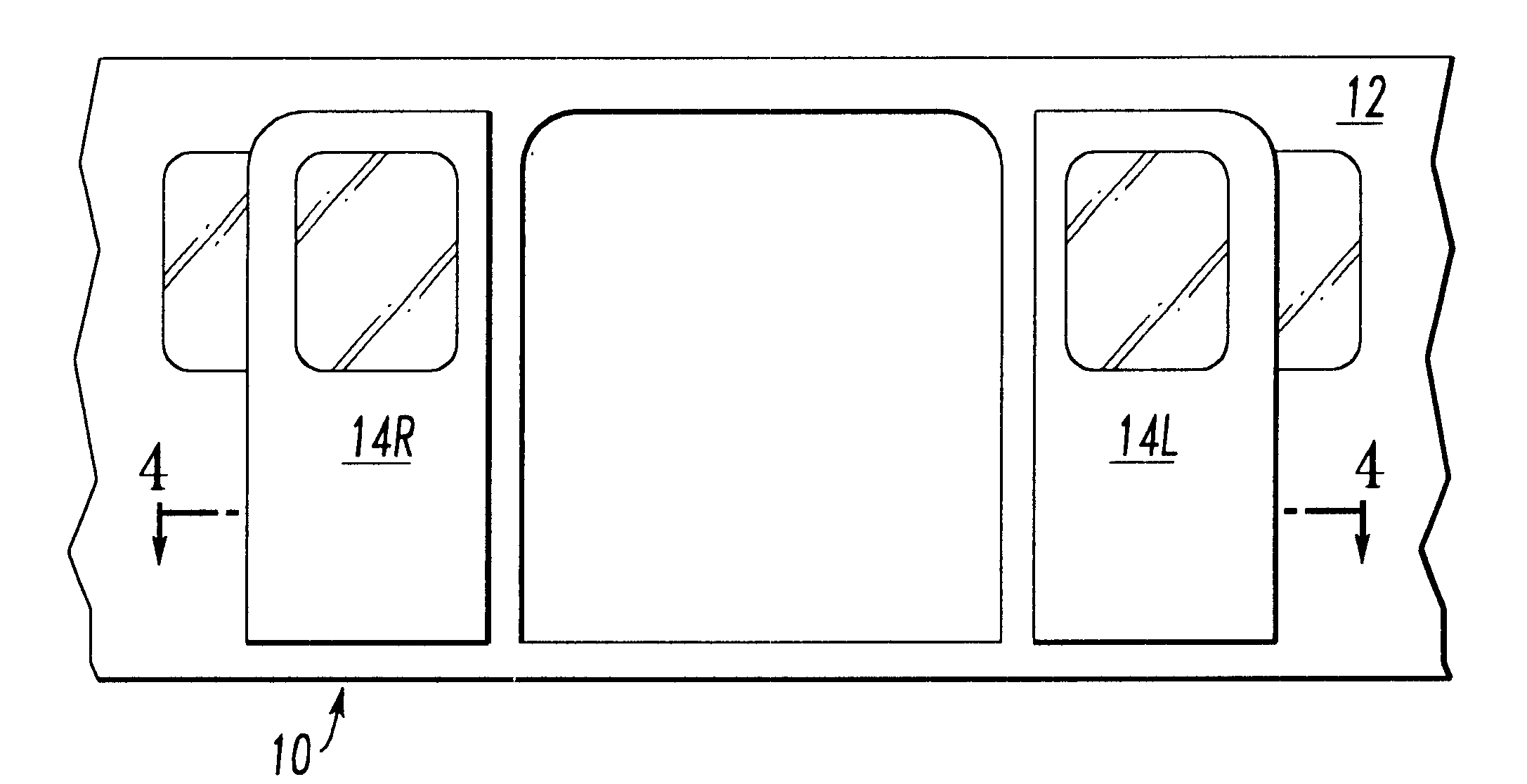
FIG. 2 is an outside elevation view of a portion of a transit vehicle having plug doors which are in their opened positions.

FIG. 3 is a horizontal section taken along line 3--3 in FIG. 1 showing the doors in their closed positions within the sidewall of the vehicle.

FIG. 4 is a horizontal section taken along line 4--4 in FIG. 2 showing curved paths on which the doors move between closed and open positions.

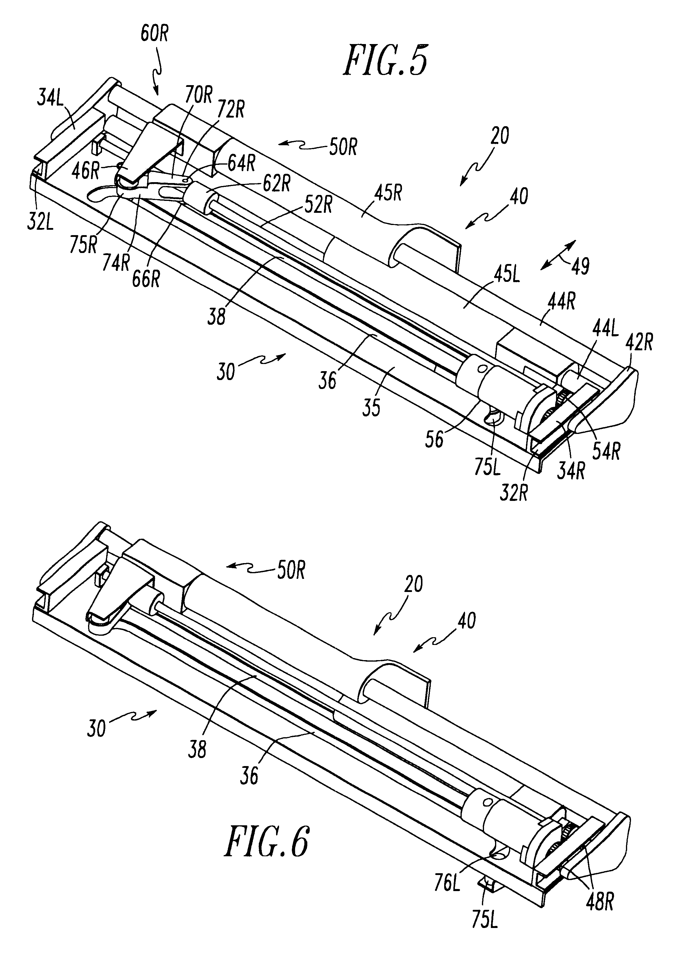
FIG. 5 is a perspective drawing of a door drive system for biparting plug doors which are positioned so that the doors would be slightly opened, the drive system being viewed from inside the vehicle.

FIG. 6 is a perspective drawing of the drive system of FIG. 5 when the doors are closed, the system being viewed from inside the vehicle.

FIG....


PUM


Abstract

Drive system for moving a load along a curved path. The drive system includes a base for mounting the drive system, the base having a curved track for guiding the load along the curved path. There is a load engaging mechanism mounted on the base for movement relative to the base, the load engaging mechanism being for moving the load. The load engaging mechanism has a curved track engaging roller for engaging the curved track. A linear drive mechanism including a linearly driven member is mounted on the base. The linearly driven member includes a driving pivot. A drive link is attached to the driving pivot at a drive force receiving end of the drive link, the drive link including a driven pivot at a drive force communicating end of the drive link. The driven pivot is attached to the load engaging mechanism, whereby linear motion of the driving pivot causes motion of the load along the curved path.

Description

The present invention relates, in general, to drive systems for moving a load along a curved track and, more particularly, the invention relates to sliding plug doors for transit vehicles.Sliding plug doors for transit vehicles require a drive system which can move the doors along curved paths. When such a door is in its closed position, it is substantially flush with the side wall of the vehicle. When it is opened, it initially moves outward and then moves longitudinally, along the wall, outside the vehicle. Such doors, generally, are guided in that curved motion by rollers engaging a curved track.A drive for such a door includes a motor connected to a power conversion unit which applies motive power in both the outward and longitudinal directions, so that the door travels along the curved track.U.S. Pat. No. 5,893,236 Power Operator for Sliding Plug Doors teaches a door drive employing a planetary gear drive. The planetary gear drive is powered by an electric motor connected to th...

Claims


Application Information

Patent Timeline
Patent Type & Authority Patents(United States)
IPC IPC(8): B61D19/00E05D15/10E05F15/14E05F17/00E05F11/34
CPCB61D19/008E05D15/1044E05D15/1068E05F15/638E05F15/652E05Y2201/64E05D2015/1055E05D2015/1071E05F17/004E05Y2201/22E05Y2201/434E05Y2201/604E05Y2201/624E05Y2201/686E05Y2800/264E05Y2900/51E05Y2201/608Y10T16/35E05D15/08E05Y2800/102E05Y2201/238E05Y2201/696
Inventor HEIDRICH, PETEROAKLEY, ROBERT L.
Owner WESTINGHOUSE AIR BRAKE TECH CORP
Why Eureka
Try Eureka