Embolic coil hydraulic deployment system with purge mechanism

a technology of hydraulic deployment system and embolic coil, which is applied in the field of medical devices, can solve the problems of high restriction of the flow of viscous fluids

Inactive Publication Date: 2003-04-08
CODMAN & SHURTLEFF INC
View PDF75 Cites 64 Cited by
  • Summary
  • Abstract
  • Description
  • Claims
  • Application Information

AI Technical Summary

Problems solved by technology

The aperture is sized such that air can pass through the aperture when fluid pressure is applied to the interior of the catheter but the flow of more viscous fluids is highly restricted.

Method used


Image

  • Embolic coil hydraulic deployment system with purge mechanism
  • Embolic coil hydraulic deployment system with purge mechanism
  • Embolic coil hydraulic deployment system with purge mechanism

Examples


Embodiment Construction

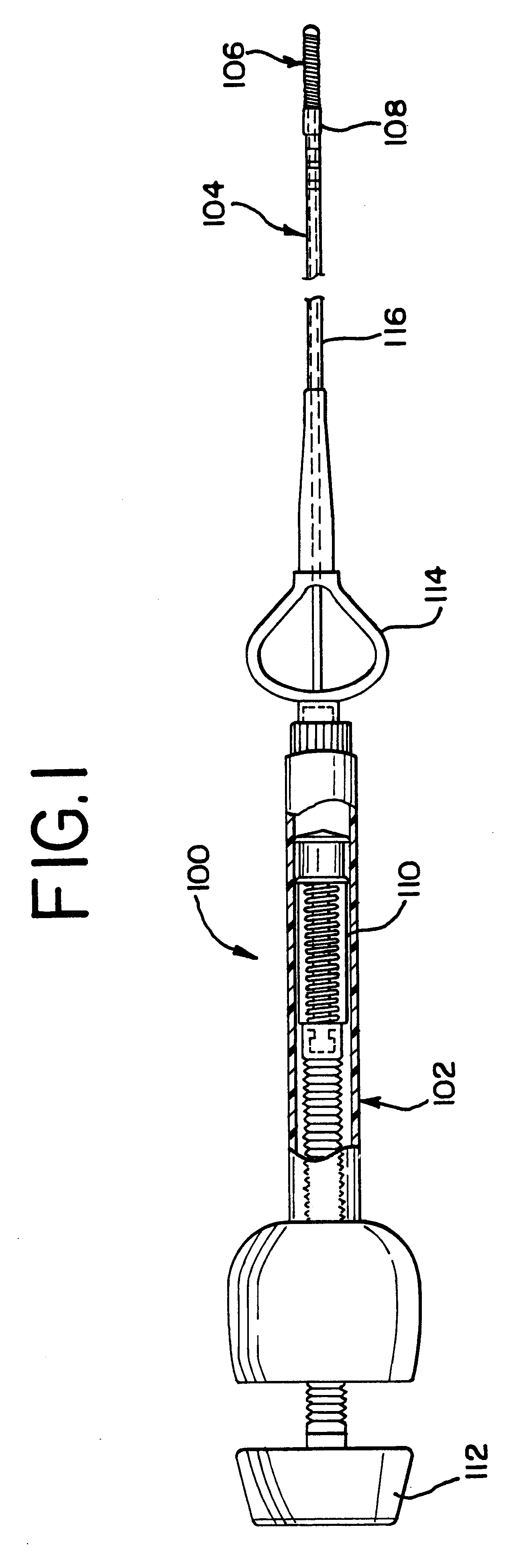
FIG. 1 generally illustrates the vascular occlusive coil deployment system 100 which is comprised of a catheter 104 having a proximal section 116 and a distal section 108, a syringe 102 coupled to the proximal section 116 of the catheter 104, and an embolic coil 106 partially disposed within the lumen of the distal section 108 of the catheter. As may be seen, the syringe 102 includes a threaded piston 110 that is controlled by a handle 112 for infusing fluid into the interior of the catheter 104. Also as illustrated, the catheter 104 includes a winged hub 114 that aids in the insertion of the catheter into the vascular system of the body.

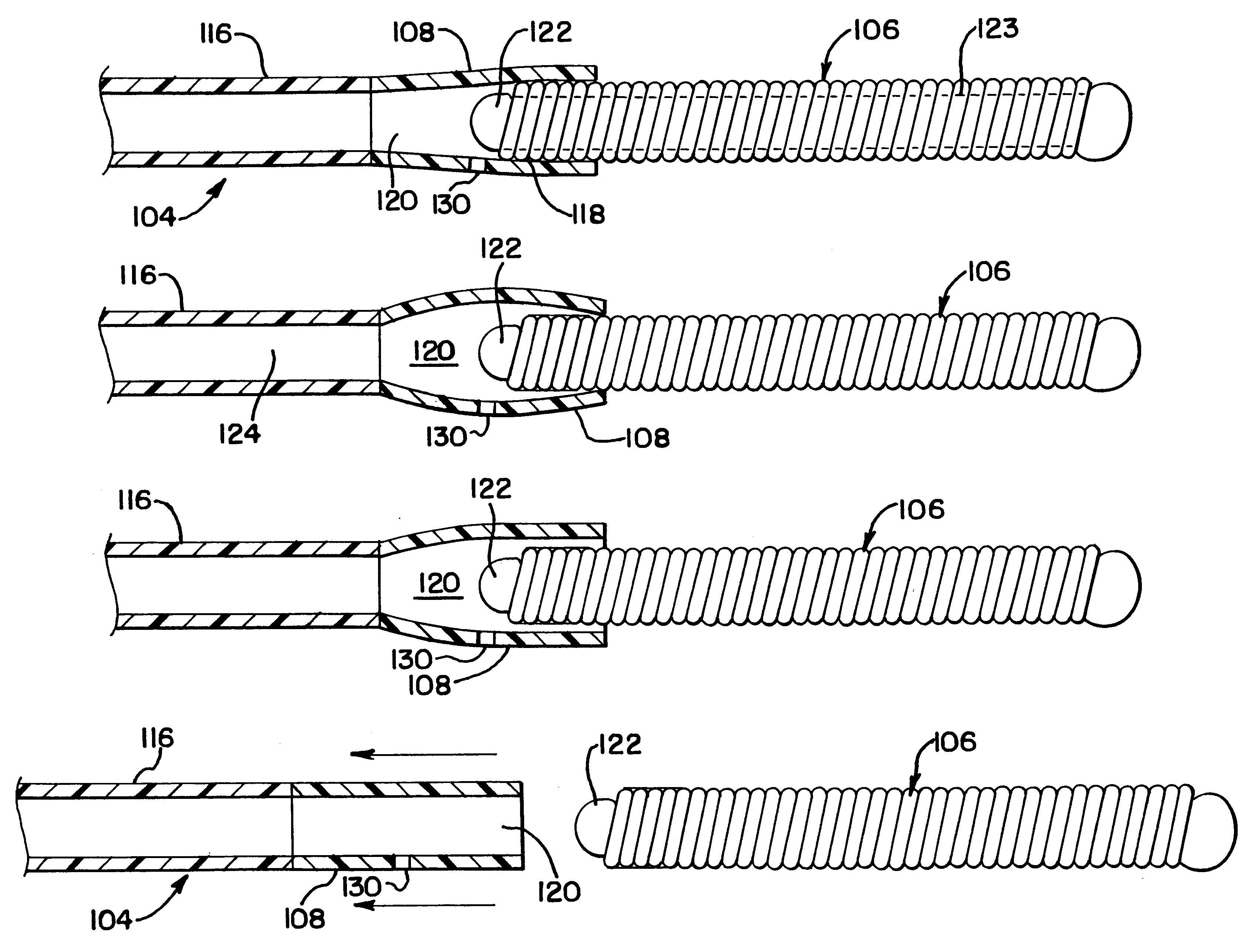
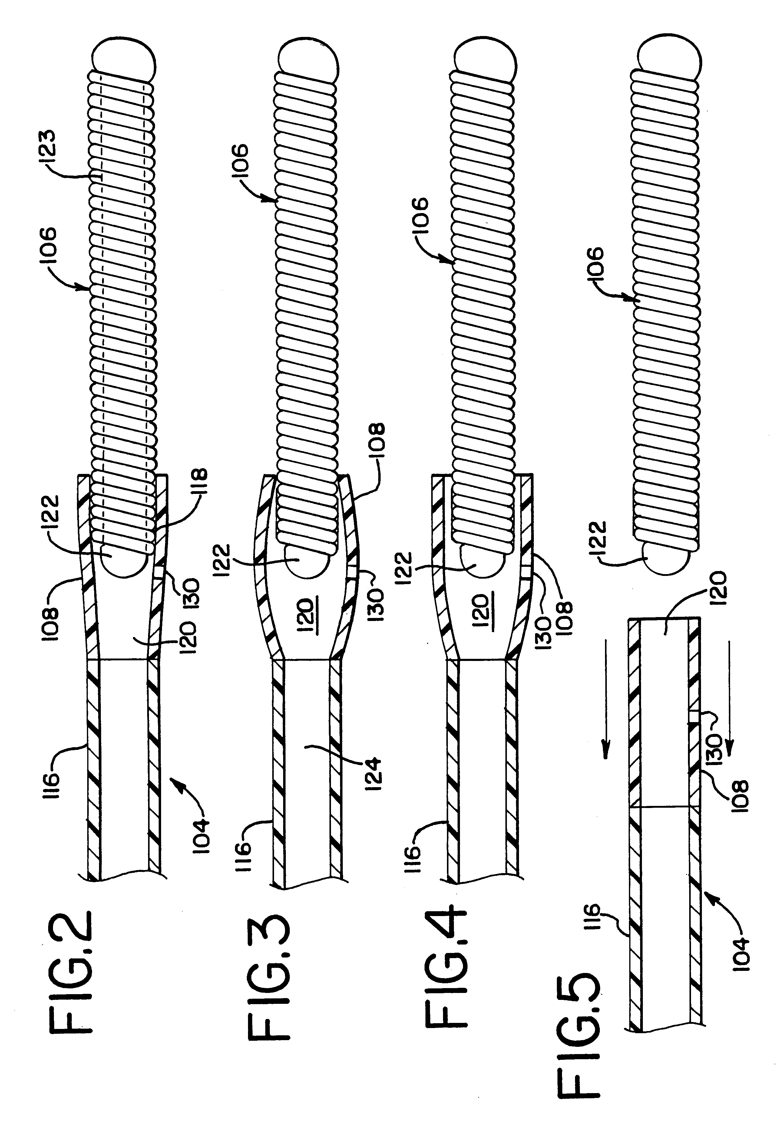
FIG. 2 illustrates in more detail the distal section 108 of the catheter 104. A proximal end 118 of the embolic coil 106 is disposed within the distal section 108 of the catheter 104 and is tightly held within the lumen 120 of this distal section 108 prior to the release of the coil. As may be appreciated, FIG. 2 illustrates the vascular occlusive c...


PUM


Abstract

A medical device for placing an embolic coil at a preselected location within a vessel comprising a positioning catheter having a distal section for retaining the embolic coil and an aperture for purging air from the device. The aperture is sized to allow air under fluid pressure to freely escape from within the catheter but to highly restrict the flow of more viscous fluids. At higher fluid pressures, the wall of the distal section expands outwardly to release the coil.

Description

1. Field of the InventionThe present invention relates generally to a medical device for placing an embolic coil at a preselected location within a vessel of the human body. More particularly, the present invention relates to a catheter system having a distal tip for retaining an embolic coil in order to transport the coil to a preselected position within the vessel and a control mechanism for releasing the embolic coil at the preselected position.2. Description of the Prior ArtFor many years, flexible catheters have been used to place various devices within the vessels of the human body. Such devices include dilation balloons, radiopaque fluids, liquid medications, and various types of occlusion devices like balloons and embolic coils.In the case of balloon catheters, prior to introducing the catheter into a human body, it is desirable to purge air from the catheter with a liquid to prevent the air from being introduced into blood vessels. In the past, purging the catheter involved...

Claims


Application Information

Patent Timeline
Patent Type & Authority Patents(United States)
IPC IPC(8): A61B17/12A61M25/00A61B17/00
CPCA61B17/12022A61B17/1214A61M25/0069A61B2017/12081A61B2017/00539
Inventor LULO, ROBERTNAGLREITER, BRETT E.
Owner CODMAN & SHURTLEFF INC
Why Eureka
Try Eureka