
Method and apparatus for panoramic imaging

a panoramic imaging and apparatus technology, applied in the field of imaging systems, can solve the problems of high cost of use of a multiple camera panoramic imaging system, distortion of reconstructed image, and possible reconstruction errors

Inactive Publication Date: 2003-04-08
SRI INTERNATIONAL
View PDF3 Cites 45 Cited by
  • Summary
  • Abstract
  • Description
  • Claims
  • Application Information

AI Technical Summary

Problems solved by technology

Such a reconstruction often results in distortions in the reconstructed image, which is arranged to be projected onto a projection surface for viewing.
That is, reconstruction errors are likely to occur.
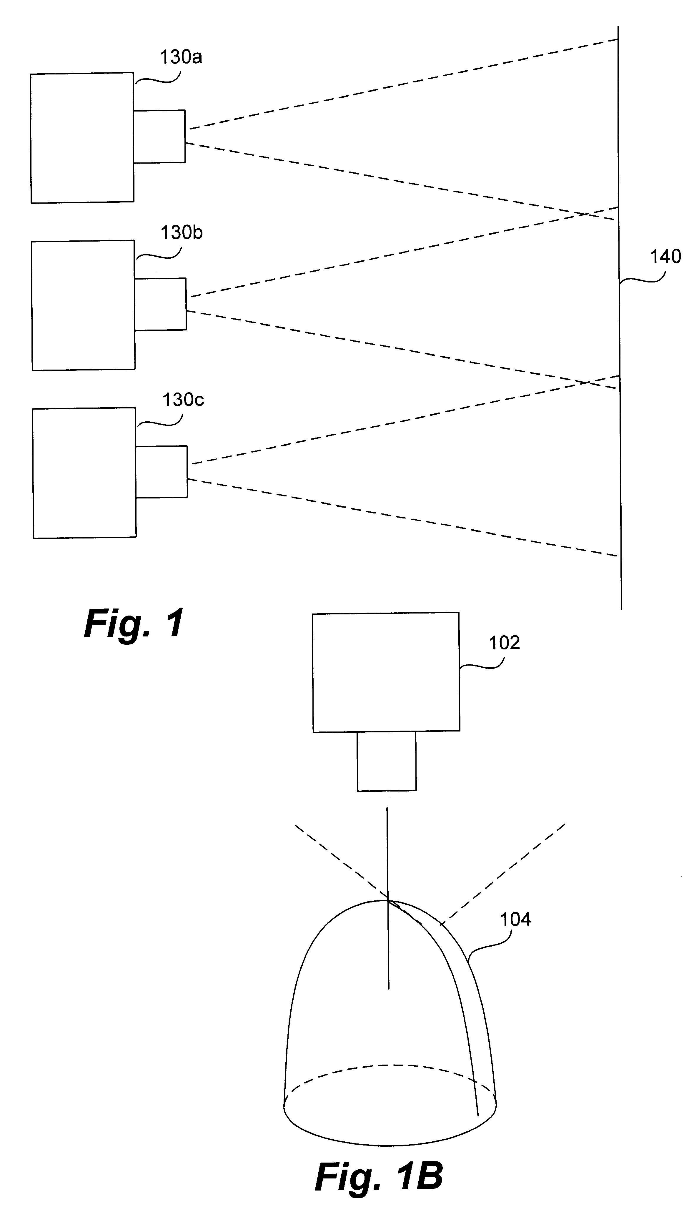
Further, the use of a multiple camera panoramic imaging system may be expensive, and requires a significant amount of physical space, as such a system requires multiple cameras 130.
On the other hand, while panoramic imaging systems with paraboloidally or hyperboloidally shaped mirrored surfaces are typically characterized by single-viewpoints, such mirrored surfaces are difficult to form.
Although mirrors curved as paraboloids and hyperboloids are relatively difficult to manufacture and, hence, expensive, panoramic imaging systems which use such mirrors are single-viewpoint systems.
For delicate applications such as surgical applications, minimizing the amount of distortion associated with a reconstructed image often proves to be critical.
By way of example, when a viewed, reconstructed image is inaccurate, or otherwise has a high level of distortion, a surgeon who is relying on the reconstructed image may make errors in a surgical procedure.

Method used


Image

  • Method and apparatus for panoramic imaging
  • Method and apparatus for panoramic imaging
  • Method and apparatus for panoramic imaging

Examples


Embodiment Construction

Panoramic imaging systems are used in various applications including, but not limited to, surveillance applications. In order to reduce the amount of distortion in a reprojected image created from a panoramic imaging system, many systems use cameras with telecentric lenses, which are costly. Many systems also use paraboloidally or hyperboloidally shaped mirrors, which are difficult to manufacture and relatively expensive, to allow optical rays to converge at a single viewpoint, thereby reducing the amount of distortion in an image once the image is reconstructed. Although spherically shaped mirrors are easier to manufacture and less expensive than paraboloidally or hyperboloidally shaped mirrors, a panoramic imaging system with a spherically shaped mirror is not a single-viewpoint system. Instead, a panoramic imaging system with a spherically shaped mirror is a multiple-viewpoint system, i.e., has more than one virtual viewpoint.

By mathematically creating a single viewpoint for a mu...


PUM


Abstract

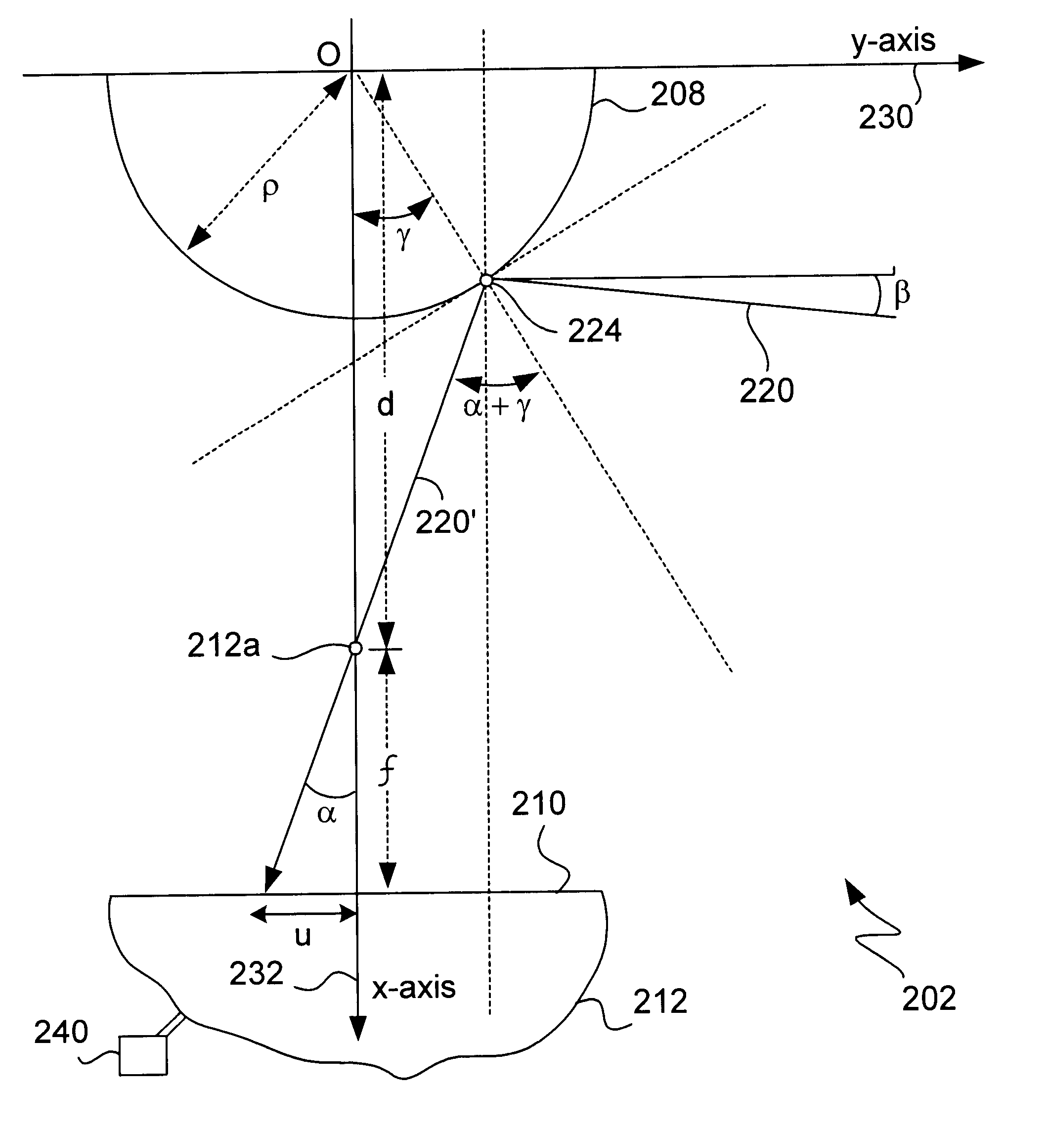
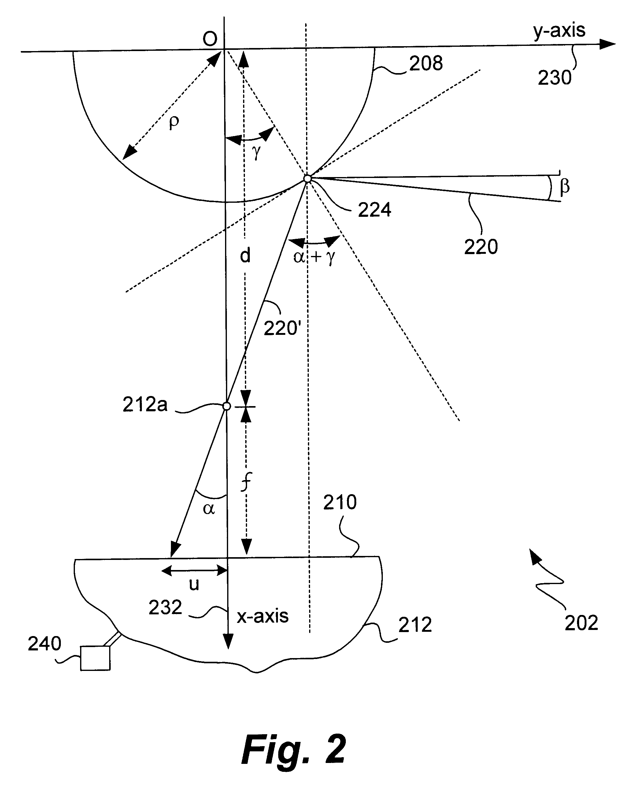
Methods and apparatus for mapping images obtained using a multiple-viewpoint imaging system are disclosed. According to one aspect of the present invention, a method for projecting an image using a panoramic imaging device which includes a first camera includes selecting a single viewpoint that is near a plurality of virtual viewpoints associated with the device. Once the single viewpoint is selected, an optical ray which intersects a surface of the device at a first angle is selected from the plurality of optical rays. The optical ray is then moved or otherwise displaced so that it intersects the single viewpoint while substantially maintaining the first angle. Once the optical ray is displaced, an image is formed using the displaced optical ray to create a reprojection from the single viewpoint. In one embodiment, the panoramic imaging device includes a spherical mirror, and the first camera includes a perspective lens. By reprojecting an image from a single viewpoint, the distortion associated with a multiple-viewpoint system may be reduced.

Description

1. Field of InventionThe present invention relates generally to imaging systems. More particularly, the present invention relates to constructing an approximation of an image obtained using a single-viewpoint imaging system when the image is actually obtained through the use of a non-single-viewpoint imaging system.2. Description of the Related ArtPanoramic imaging is often used in imaging applications due to the fact that panoramic imaging systems provide a relatively wide field of view. Although panoramic imaging systems may be used for a variety of different purposes, such systems are generally used in applications which benefit from a wide field of view. Such applications often relate to, but are not limited to, the areas of surveillance, robotics, and machine vision.In general, panoramic imaging systems include devices which are capable of imaging a wide angle of a scene. The wide angle may be up to approximately 360 degrees as measured as both an azimuth and an elevation. Ofte...

Claims


Application Information

Patent Timeline
IPC IPC(8): G02B13/06H04N5/225
CPCG02B13/06H04N5/23238H04N5/2254H04N23/55H04N23/698
Inventor KONOLIGE, KURTDERRIEN, STEVEN
Owner SRI INTERNATIONAL
Learn More