Clamping device for formwork panels

a technology of formwork and clamping device, which is applied in the direction of rod connection, manufacturing tools, building scaffolds, etc., can solve the problems of complicated and unwieldy support device, complicated use of existing devices, and leakage of honeycomb or ridges on finished concrete, etc., and achieves the effect of convenient assembling and disassembly

Inactive Publication Date: 2003-04-15
CONCRETE FORM HIRE +1
View PDF18 Cites 9 Cited by
  • Summary
  • Abstract
  • Description
  • Claims
  • Application Information

AI Technical Summary

Benefits of technology

It is an object of the invention to provide a clamping device to hold adjacent formwork panels, with the clamping device being simple, robust and easy to assemble and disassemble.
It is a further object of the invention to provide a clamping device for formwork panels which may overcome the abovementioned disadvantages or provide the public with a useful or commercial choice.
The above arrangement is-simple and can be used to clamp formwork panels to form corners of 90.degree., 45.degree., or any other angle, and can also be used, if desired, to clamp adjacent panels in a straight line.
To provide a good, strong, secure connection between the rod and the backing plate, the rod can be attached to a boss or protrubance which itself is attached to the backing plate.
If the rod is attached to a protrubance, the protrubance may have sides against which edges of the formwork abut. This arrangement can minimise movement of the formwork panels, and can also serve to align the formwork panels and the clamping device.

Problems solved by technology

Any leaks can produce honeycombing or ridges on the finished concrete.
Angled formwork, that is where adjacent formwork panels meet at an angle, require special consideration, and to date, complicated and unwieldy support devices are used to clamp formwork panels together at an angle.
These existing devices are complicated to use, and readily become unusable should minimum contamination occur.
That is, should small amounts of wet cement fall on to existing devices, the devices either cease to function or must be cleaned prior to use.

Method used


Image

  • Clamping device for formwork panels
  • Clamping device for formwork panels
  • Clamping device for formwork panels

Examples


Embodiment Construction

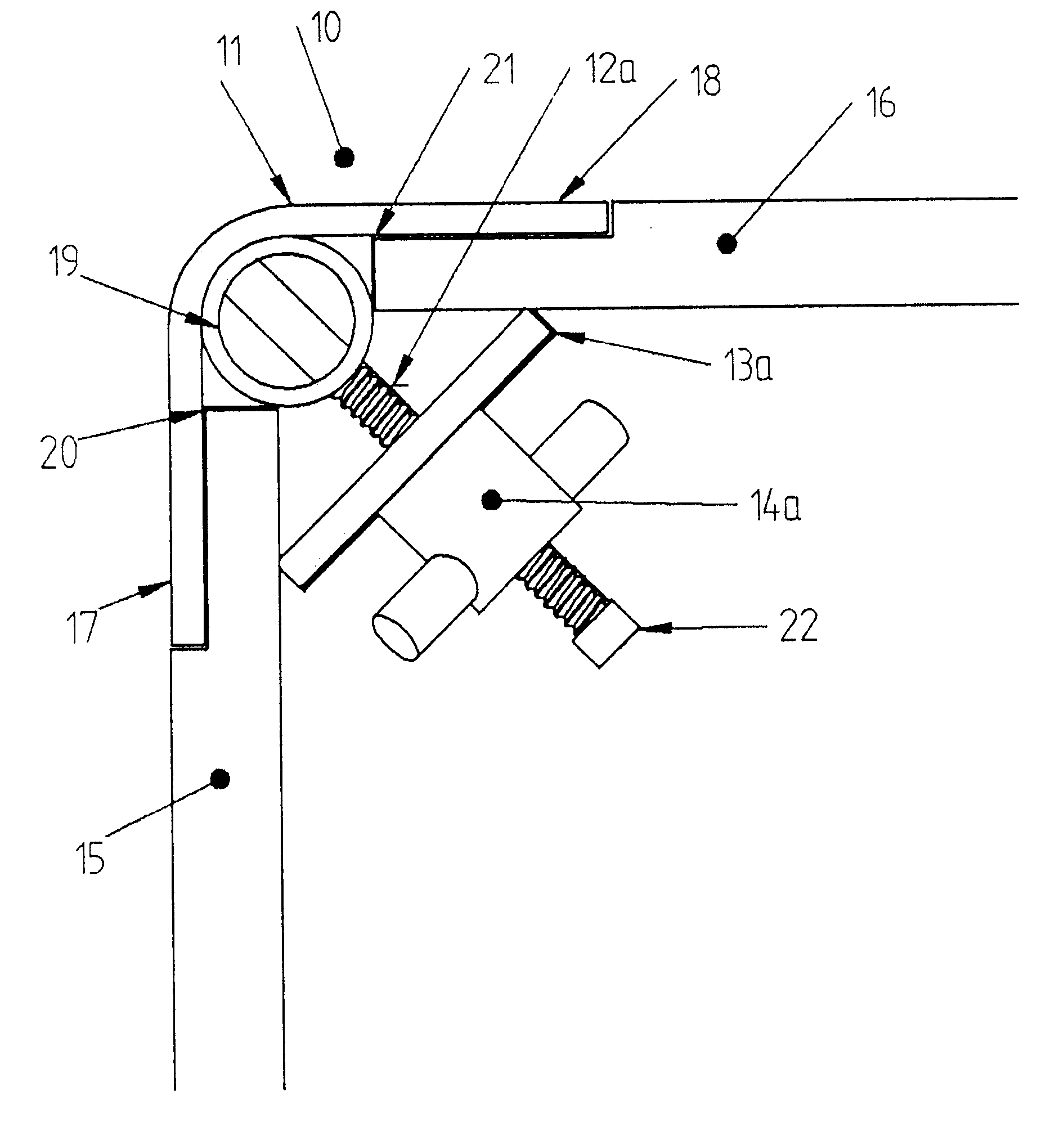
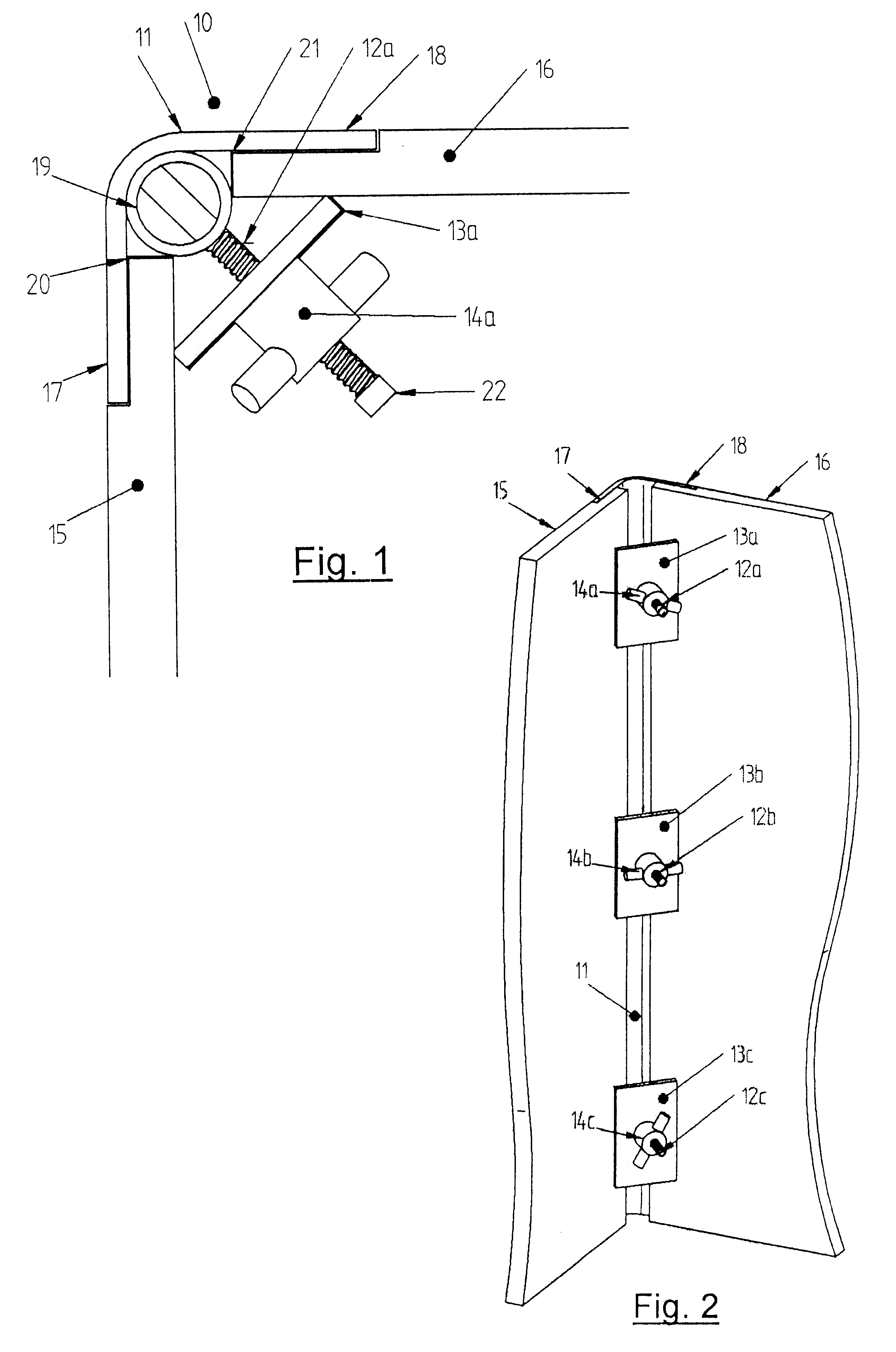
Referring to the drawings and initially to FIG. 1, there is shown a clamping device 10, which in this embodiment is of the type to form a 90.degree. corner to formwork. Clamping device 10 has a backing plate 11, and a number of rods 12A-12C extend from the backing plate. Clamping device 10 further includes a clamping member which consists of a clamping plate 13A-13C and a clamping nut 14A-14C.

Backing plate 11 is formed from an elongate steel plate and has a length the same as the height of the formwork panels, 15, 16 which are to be clamped to the clamping device 10. In the embodiment, backing plate 11 is bent into 90.degree. to define a pair of opposed flanges 17, 18. It should be appreciated however that backing plate 11 can be bent into other angles such as 45.degree. and the like or may comprise a straight plate.

Flanges 17, 18 function to allow edges of panels 15, 16 to abut against the flanges. The edges of panels 15, 16 may be rebated as illustrated to provide a flush corner f...


PUM


Abstract

A clamping device to hold adjacent formwork panels has a backing plate against which edges of the adjacent formwork panels can be held, at least one rod extending from the backing plate, and a clamping member able to move along the rod between a clamping position where the member clamps the formwork panels against the backing plate, and a free position where the formwork panels can be removed.

Description

This invention relates to a clamping device for formwork, which is a temporary mould in which concrete, other settable materials, rammed earth and the like can be placed. The invention will be described with reference to concrete formwork, but other uses of the formwork are envisaged.The function of formwork is to hold fluid concrete into the desired shape, to support fresh concrete until it is strong enough to be self-supporting, and to support temporary loading such as runways and machinery used to place the concrete.Formwork should be simple to erect and dismantle. Only the minimum number of fasteners should be used. The formwork must remain straight and rigid when concrete is poured and therefore adequate bracing is essential to prevent movement caused by vibrators, concrete pumps and other machinery. The formwork should be tight to prevent loss of "fines". Any leaks can produce honeycombing or ridges on the finished concrete. Formwork should also be constructed such that maximu...

Claims


Application Information

Patent Timeline
Patent Type & Authority Patents(United States)
IPC IPC(8): E04G17/04E04G17/00
CPCE04G17/001E04G17/04Y10T403/73Y10T403/46Y10T403/4602F16B2200/67
Inventor RAE-SMITH, CLIFFORD JOHN
Owner CONCRETE FORM HIRE
Why Eureka
Try Eureka