Resonator device, filter, composite filter device, duplexer, and communication device
a technology of composite filter and resonator, which is applied in the direction of resonators, electrical devices, waveguides, etc., can solve the problem of large filter overall siz
- Summary
- Abstract
- Description
- Claims
- Application Information
AI Technical Summary
Problems solved by technology
Method used
Image
Examples
first embodiment
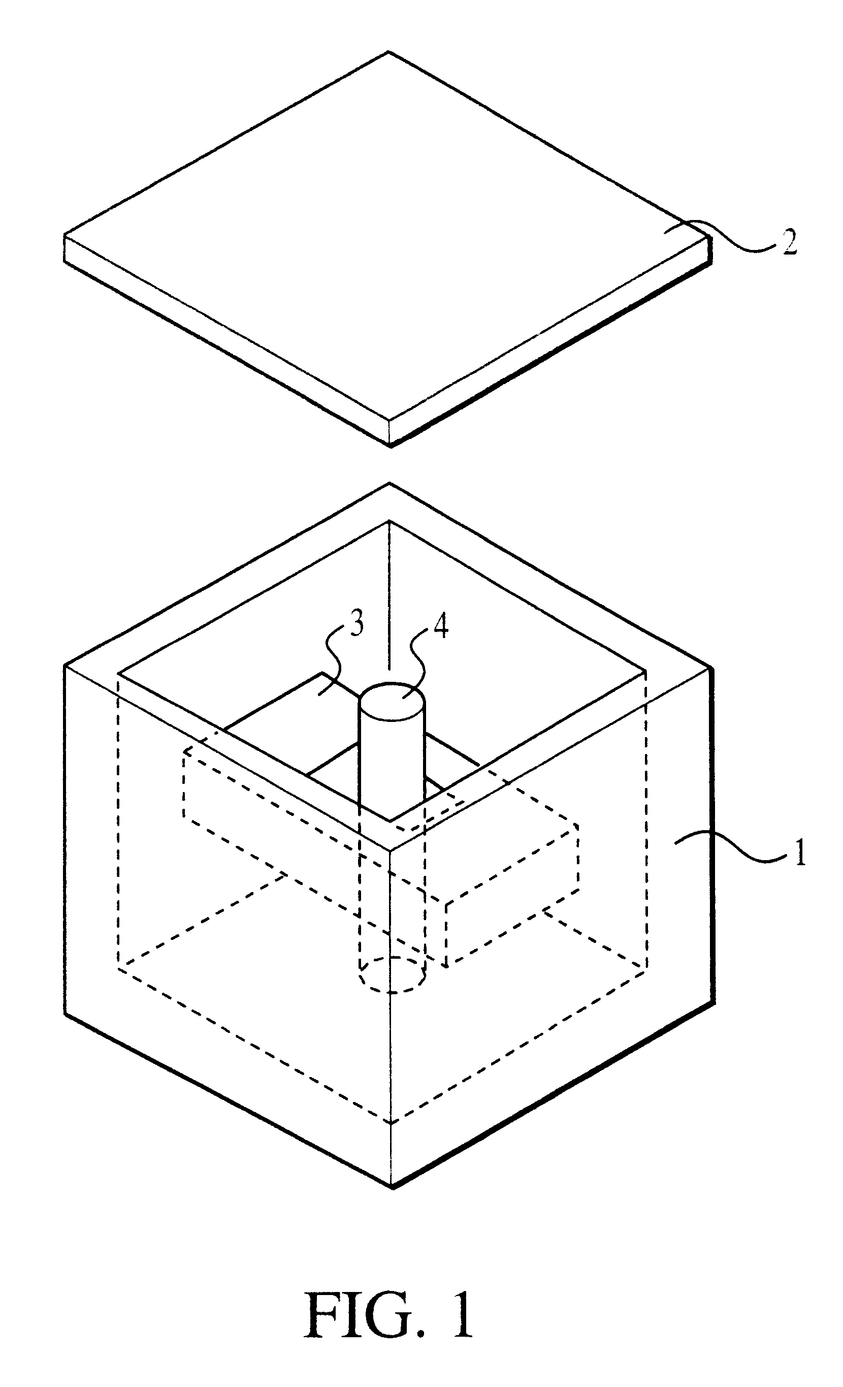
The configuration of a resonator device according to the present invention will be described with reference to FIGS. 1 to 4.
FIG. 1 is an exploded perspective view of the resonator device. In FIG. 1, the resonator device contains a cavity body 1 having a substantially rectangular parallelepiped shape of which the upper side is open, and the underside is closed, and a cavity lid 2 covering the open upper side of the cavity body 1. A conductor rod 4 is formed so as to protrude from the center of the inner bottom of the cavity body 1, extending in parallel to the respective inner walls of the cavity body 1. Moreover, as shown in FIG. 1, a dielectric core 3 having a substantially rectangular parallelepiped shape is provided, which has a hole which the conductor rod 4 is inserted in and through.
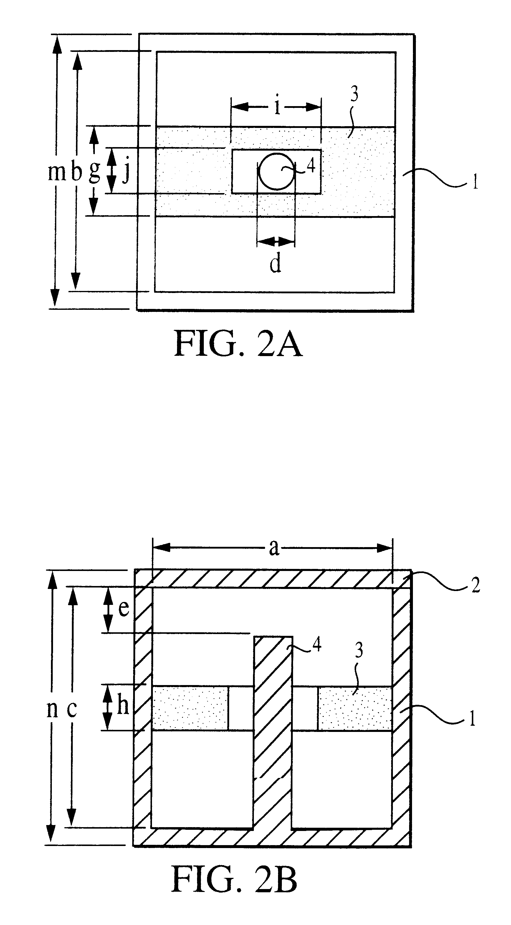
FIG. 2A is a plan view of the resonator device before the cavity lid 2 is attached. FIG. 2B is a central, longitudinal cross section of the resonator device having the cavity lid 2 attached thereto...
third embodiment
FIGS. 6A and 6B show two examples of the configuration of a resonator according to the present invention. These figures are plan views of the resonator device before the cavity lid is attached thereto. In each example, one end-face in the longitudinal direction of the dielectric core 3 is bonded to the inner wall of the cavity body 1, while the other end is spaced from the inner wall of the cavity. In such a structure, the resonator device has a characteristic which is intermediate between the characteristic of the resonator device having both of the ends in the longitudinal direction of the dielectric core 3 bonded to the inner walls of the cavity, and the characteristic of the resonator device having both of the ends of the dielectric core spaced from the inner walls of the cavity. Accordingly, a resonator having a small overall size and a high Q value can be obtained.
In FIG. 6A, the conductor rod 4 is disposed on the center axis of the cavity. As shown in FIG. 6B, the conductor r...
fifth embodiment
FIG. 8 is a perspective view showing the structure of the dielectric core 3 of a resonator device according to the present invention. The shape of the dielectric core 3, together with the cavity, constituting the resonator in the quasi-TM mode is not limited to being a rectangular parallelepiped. The shape may be another polyhedron, rather than a hexahedron, and also, may be columnar.
Moreover, by increasing the area of the center portion in the longitudinal direction of the dielectric core 3, as shown in FIG. 8, deterioration of the Q value in the TM mode is suppressed, which will be caused by effects of the conductor rod 4 passing through the center portion. Thus, the Q value can be enhanced.
PUM
 Abstract
Description
Claims
Application Information
 - R&D
- Intellectual Property
- Life Sciences
- Materials
- Tech Scout
- Unparalleled Data Quality
- Higher Quality Content
- 60% Fewer Hallucinations
Browse by: Latest US Patents, China's latest patents, Technical Efficacy Thesaurus, Application Domain, Technology Topic, Popular Technical Reports.
© 2025 PatSnap. All rights reserved.Legal|Privacy policy|Modern Slavery Act Transparency Statement|Sitemap|About US| Contact US: help@patsnap.com


