
Catadioptric lens barrel structure

a technology of catadioptric lens and barrel structure, which is applied in the direction of mountings, microlithography exposure apparatuses, instruments, etc., can solve the problems of changing the focus depth of the projection system, the design of catadioptric lens barrels, and the difficulty of keeping proper alignment of a plurality of lens barrels

Inactive Publication Date: 2003-04-15
NIKON CORP
View PDF11 Cites 22 Cited by
  • Summary
  • Abstract
  • Description
  • Claims
  • Application Information

AI Technical Summary

Problems solved by technology

This type of catadioptric lens barrel design, however, poses several problems.
First, keeping proper alignment of a plurality of lens barrels can be difficult.
Second, the focus depth of the projection system changes as temperature changes.
Errors related to these factors collectively alter the focusing properties of the optical system.
Third, the lens barrel structure tends to be more sensitive to movement or vibration than conventional single barrel designs.

Method used


Image

  • Catadioptric lens barrel structure
  • Catadioptric lens barrel structure
  • Catadioptric lens barrel structure

Examples


Embodiment Construction

Reference will now be made in detail to an embodiment of the invention, examples of which are illustrated in the accompanying drawings. Wherever possible, the same reference numbers will be used throughout the drawings to refer to the same or like parts. The invention will be further clarified by the following examples, which are intended to be exemplary of the invention.

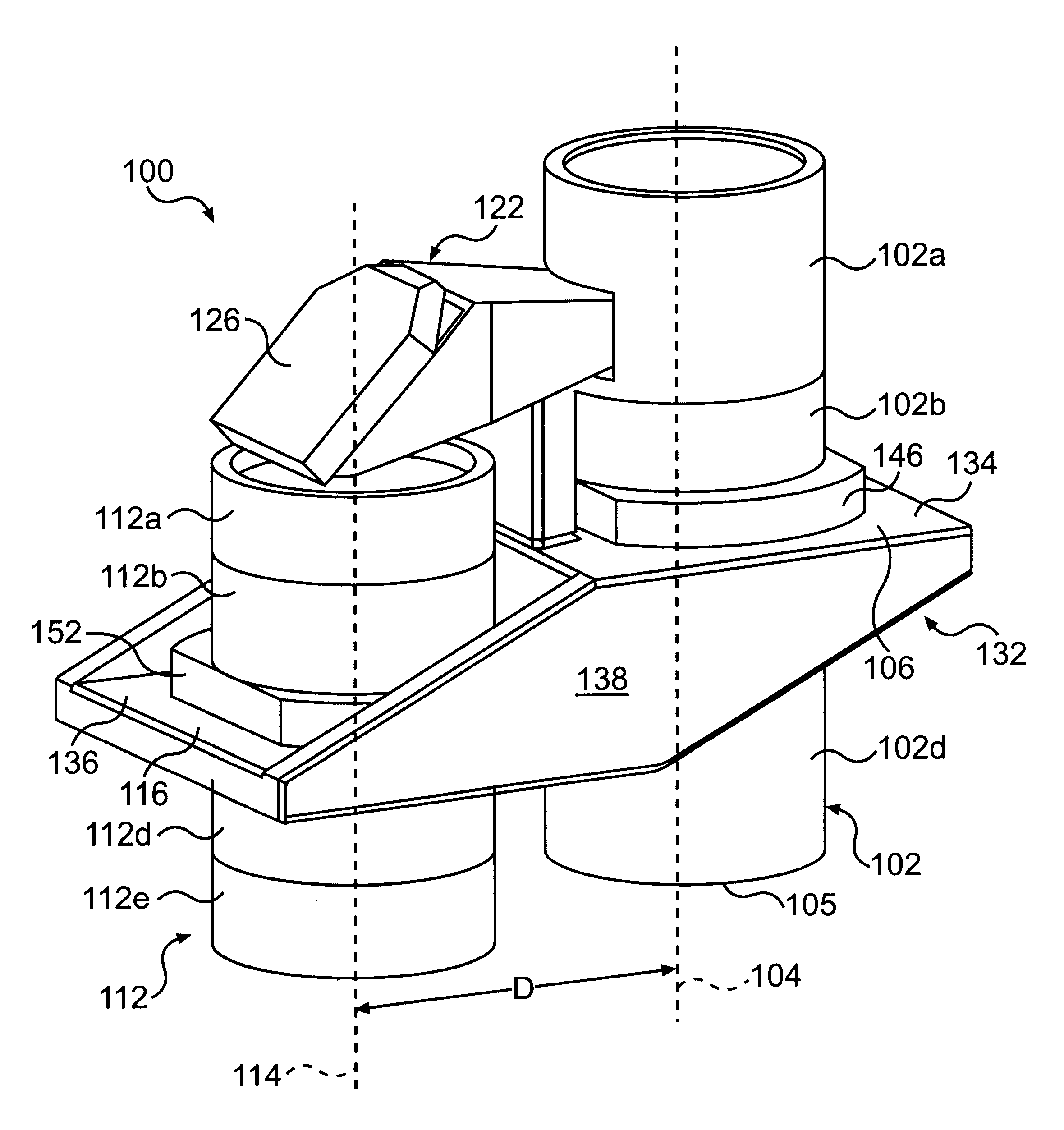
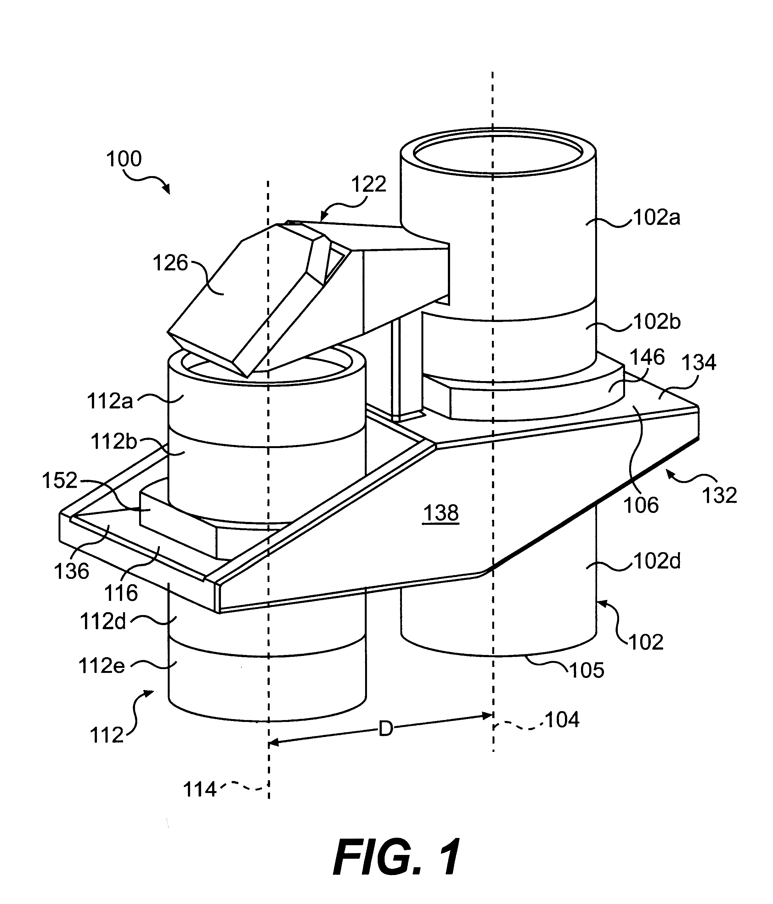
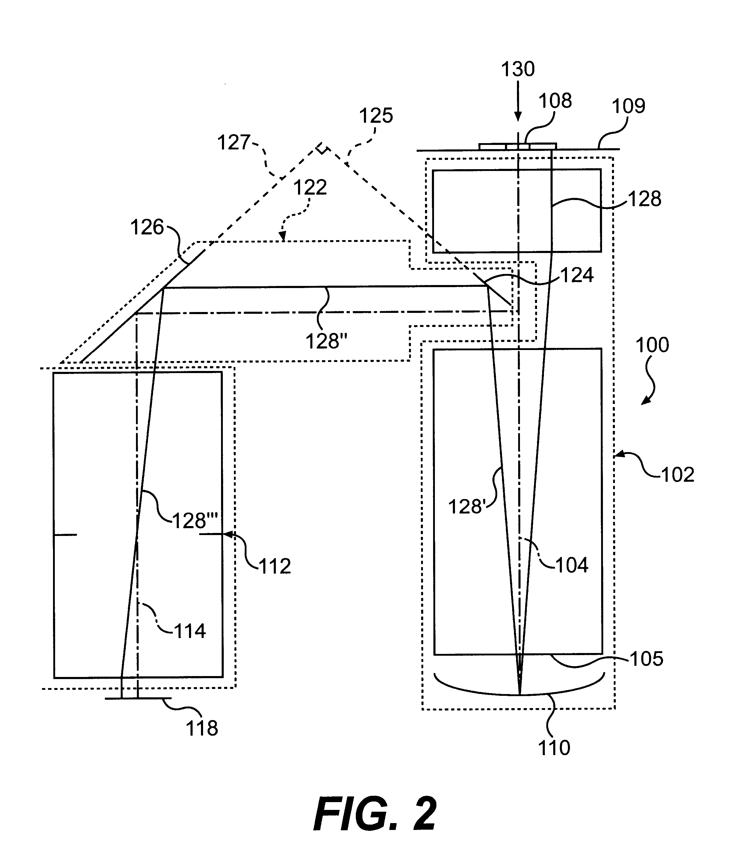
A catadioptric lens barrel structure is provided with a plurality of lens barrels and a support structure configured to provide enhanced stability and made out of materials that reduce the effects of environmental changes on the lens barrel structure. The lens barrels run parallel to each other. Each lens barrel has a center plane perpendicular to the length of the lens barrel and crossing the lens barrel at its mid-length. The support structure supports each of the lens barrel substantially near the corresponding center plane, which provides enhanced stability of the lens barrel structure. The support structure is ...


PUM


Abstract

A catadioptric lens barrel structure for a projection exposure apparatus includes first and second lens barrels. Each of the lens barrels has an optical axis. The optical axes run parallel to each other. The lens barrel structure also includes a third lens barrel transversely connecting the first lens barrel to the second lens barrel. A reticle is placed in front of an entrance end of the first lens barrels and a wafer is placed in front of an exit end of the second lens barrel. Each lens barrel has a center plane perpendicular to the corresponding optical axis at a position half-way along the length of the corresponding lens barrel. A lens barrel support structure firmly secures the plurality of lens barrels. The lens barrel support structure is made of a material having a low coefficient of thermal expansion. The support structure includes first and second support platforms to support the first and second lens barrels, respectively, near the corresponding center planes to minimize errors due to temperature changes, vibrational motion, or other external forces.

Description

1. Field of the InventionThis invention relates to a catadioptric lens barrel which can be attached to an optical projection unit, such as a projection exposure apparatus used to manufacture semiconductor wafers. More particularly, the present invention relates to a catadioptric lens barrel structure including its support structure, the lens barrel structure comprising a plurality of lens barrels aligned in parallel, and at least one transverse lens barrel connecting the plurality of lens barrels.2. Description of the Related ArtA lens barrel is a tubular mechanical structure containing a series of lenses which are aligned to transfer an image from one end of the lens barrel to the other. The lens barrel may include a sturdy threaded body and durable metal retaining rings, often referred to as "sub-barrels," to carry a series of lens holders, commonly referred to as "cells." One type of lens barrel is known as a catadioptric lens barrel. A catadioptric lens barrel contains not only ...

Claims


Application Information

Patent Timeline
IPC IPC(8): G02B17/08G03F7/20
CPCG02B17/08G03F7/70225G02B17/0892
Inventor SPINALI, MARC
Owner NIKON CORP
Learn More