Measuring instruments

a technology of measuring instruments and measuring cylinders, which is applied in the direction of measuring devices, mechanical measuring arrangements, instruments, etc., can solve the problems of difficult to change the measuring force in accordance with the material and workpiece configuration, and achieve the effect of improving the accuracy and accuracy of the measuremen

Inactive Publication Date: 2003-04-29
MITUTOYO CORP
View PDF25 Cites 21 Cited by
  • Summary
  • Abstract
  • Description
  • Claims
  • Application Information

AI Technical Summary

Benefits of technology

According to the measuring instrument, when the screwing position of the biasing force adjuster screwed to the sleeve is changed, since the distance from the biasing force adjuster to the connector changes, the compression of the biaser accommodated therebetween changes. Accordingly, the preload can be changed with a simple arrangement.
According to the above measuring instrument, since the window since the window for exposing the scale is provided to the cover, the scale can be visually checked through the window. In other words, the scale can be visually checked while preventing fluctuation of the screwing position of the biasing force adjuster on account of contact to the biasing force adjuster.

Problems solved by technology

However, though the constant measuring force can be maintained during measurement by the conventional measuring instrument, it is practically difficult to change the measuring force in accordance with the material and configuration of the workpiece.

Method used


Image

  • Measuring instruments
  • Measuring instruments
  • Measuring instruments

Examples


first embodiment

[First Embodiment]

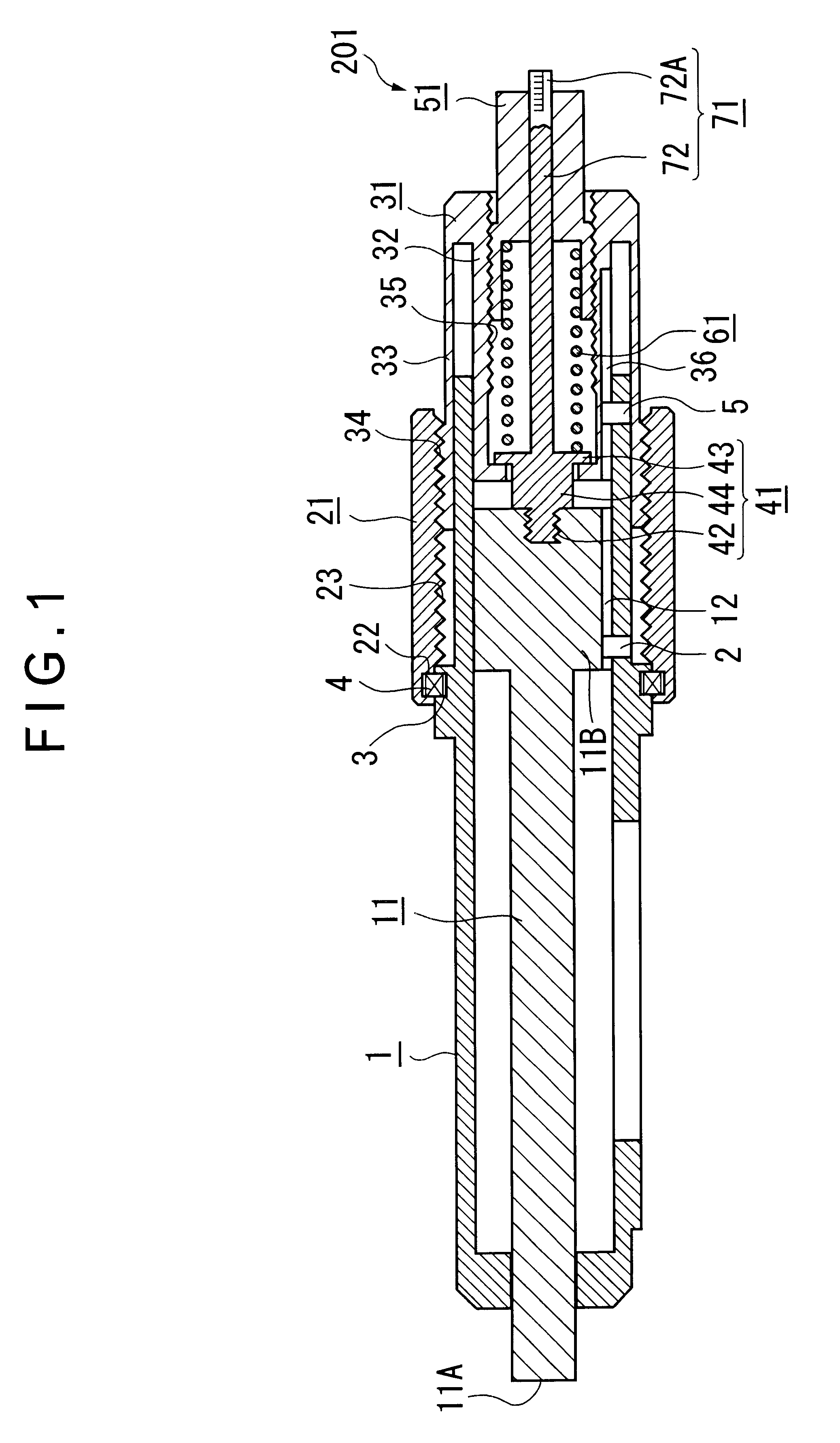
FIG. 1 shows a first embodiment. The measuring instrument of the first embodiment has a cylindrical body 1, a spindle 11 provided inside the body 1, a thimble 21 provided outside the body 1, a sleeve 31 movable in the same direction as the moving direction of the spindle 11 and stoppable at any position, a connector 41 for connecting the sleeve 31 with the spindle 11, a biasing force adjuster 51, a pressure spring 61 as a biasing means, a biasing force indicator 71 and a position detecting indicator (not shown).

The spindle 11 is provided inside the body 1 to be movable in the axial direction and has a distal portion 11A projecting from the body 1. A key groove 12 slidably fitted to a key pin 2 projecting on the inner circumference of the body 1 is formed on a base end 11B of the spindle 11 along the axial direction. Accordingly, the spindle 11 is held by the body 1 while being movable in the axial direction and unable to rotate. Incidentally, reverse arrangement of...

second embodiment

[Second Embodiment]

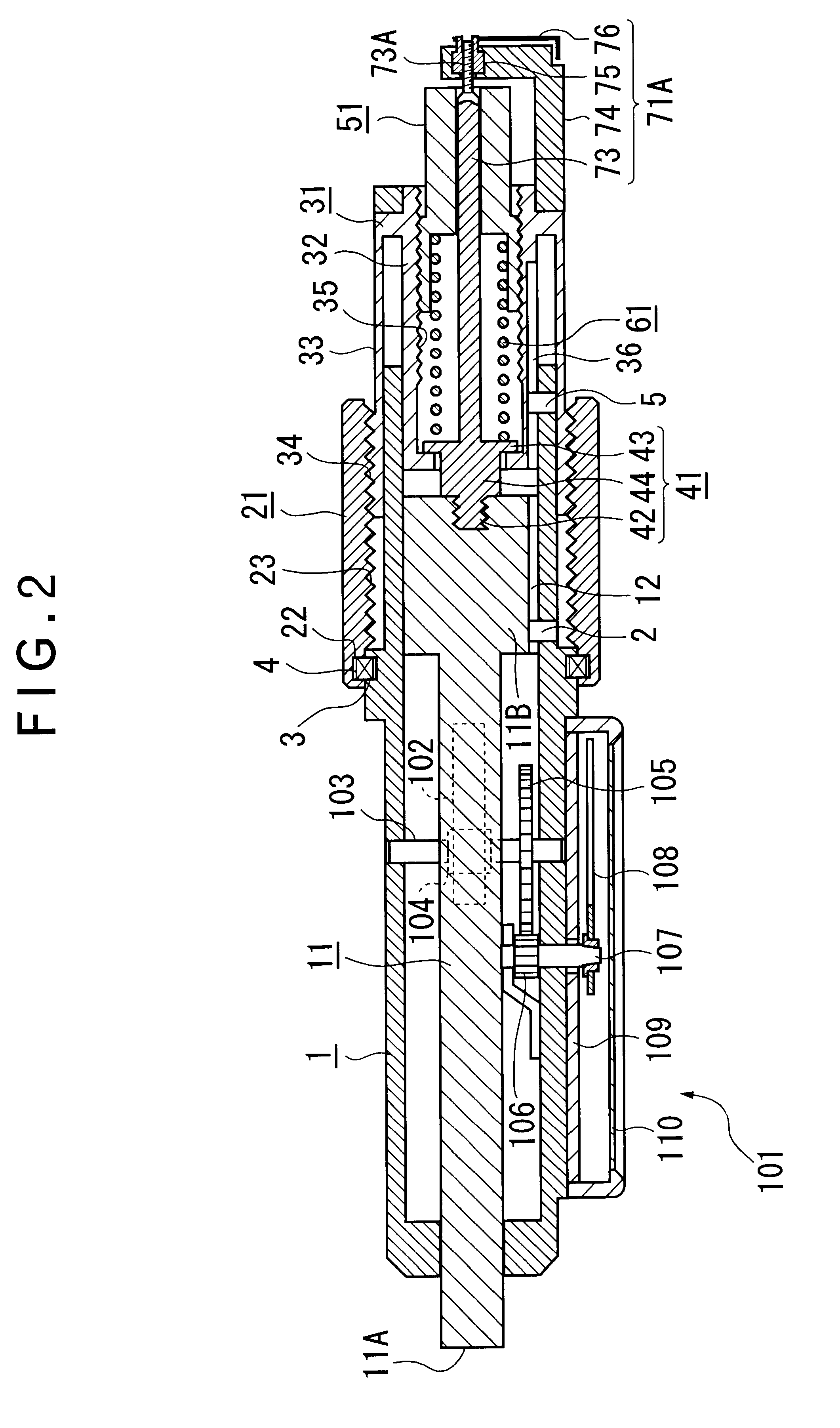
FIG. 2 shows a second embodiment. The measuring instrument according to the second embodiment has a biasing force indicator arranged differently from the measuring instrument of the first embodiment and additionally has a position detecting indicator 101 for detecting the moving position of the spindle 11 as a rotary angle of an index.

A biasing force indicator 71A of the present embodiment has a threaded shaft 73 projected from the connector 41 penetrating the biasing force adjuster 51 and having an external thread 73A, a nut 75 screwed to the threaded shaft 73 and provided to an arm 74 in a manner rotatable and immovable in the axial direction thereof, and an index 76 fixed to the nut 75.

The position detecting indicator 101 has a rack 102 formed along the axial direction of the spindle 11, a pinion 104 meshed with the rack 102 and rotatably supported by the body 1 through a shaft 103, a gear 105 fixed to the shaft 103 of the pinion 104, a gear 106 meshing with th...

third embodiment

[Third Embodiment]

FIG. 3 shows a third embodiment. The measuring instrument according to the third embodiment has a biasing force indicator arranged differently from the measuring instrument of the first embodiment and additionally has a position detecting indicator 111 for detecting the moving position of the spindle 11 as an electric signal.

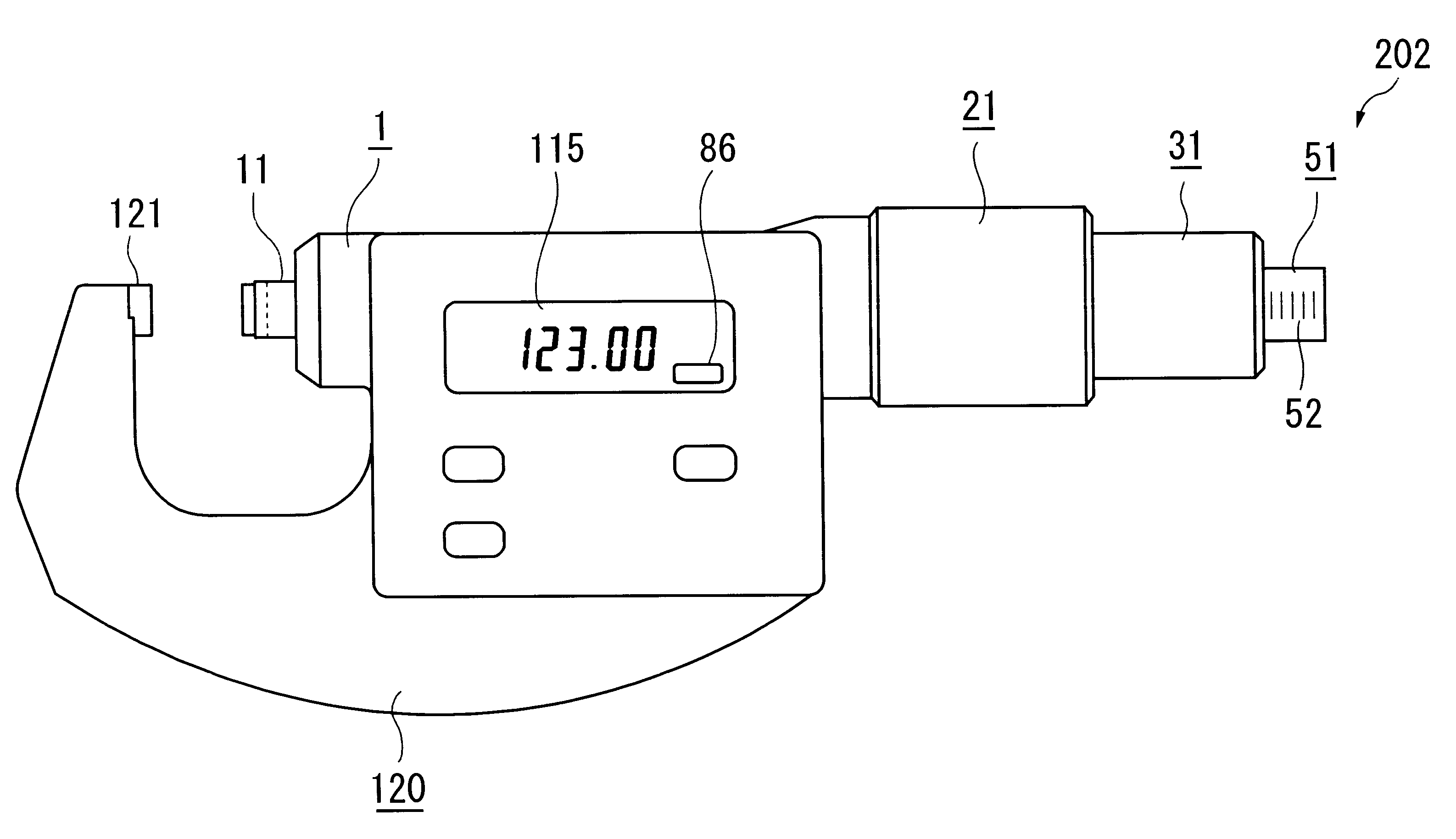
The position detecting indicator 11 has a scale 112 provided to the spindle 11, a detection scale 113 opposingly provided to the body 1 spaced from the scale 112 with a predetermined gap, a detecting circuit 114 for detecting relative displacement of the scales 112 and 113 as an electric signal, and a digital display 115 for digitally displaying the relative displacement detected by the detecting circuit 114.

A biasing force indicator 71B includes a detection switch 81 for detecting approach of the spindle 11 and the sleeve 31 for a predetermined distance, and a display 86 (arranged as a part of the digital display 115) for displaying the actuat...


PUM


Abstract

A measuring instrument includes a spindle (11) provided to a body (1), a sleeve (31) movable in the same direction as the spindle and stoppable at a desired position, a connector (41) for connecting the sleeve and the spindle and allowing relative movement of the sleeve and the spindle in the moving direction thereof by a predetermined stroke; a pressure spring (61) accommodated in the sleeve for biasing the spindle in a direction for the spindle to abut to the workpiece through the connector, and a biasing force indicator (71) for indicating the pressure spring.

Description

1. Field of the InventionThe present invention relates to a measuring instrument for bringing a spindle into contact with a workpiece to measure the dimension of the workpiece based on the moving position of the spindle. More specifically, it relates to a measuring instrument having a body and a spindle provided to the body movable in the axial direction of the body, in which the spindle is brought into contact with the workpiece by moving the spindle in the axial direction to measure the dimension of the workpiece, the measuring instrument being capable of displaying measuring force.2. Description of Related ArtA measuring instrument having a spindle movably provided to a body to be in contact with a workpiece for detecting a dimension of the workpiece such as, for instance, a micrometer, also has a ratchet mechanism for bringing the spindle into contact with the workpiece at a constant force as well as a thimble for advancing and retracting the spindle in the axial direction there...

Claims


Application Information

Patent Timeline
Patent Type & Authority Patents(United States)
IPC IPC(8): G01B3/18G01B5/02G01B21/02
CPCG01B3/18
Inventor NISHINA, SHINGOTACHIKAKE, MASAHIKOSHIRAISHI, YOSHIAKITANAKA, RIEHAYASHIDA, SHUUJIKUJI, YOSHITAKASAITO, OSAMUNAKADOI, TETSUYA
Owner MITUTOYO CORP
Why Eureka
Try Eureka