
Image generation system, image display system, computer-readable record medium recording image generation program, and image generation method

a technology of image generation and image display system, which is applied in the field of image generation system, image display system, computer-readable record medium recording image generation program, and image generation method, can solve the problems of large computation load on a computer, inability to generate an image in real-time cg on a general-purpose computer, and inability to display human beings, animals, plants,

Inactive Publication Date: 2003-04-29
MITSUBISHI ELECTRIC CORP
View PDF5 Cites 31 Cited by
  • Summary
  • Abstract
  • Description
  • Claims
  • Application Information

AI Technical Summary

Benefits of technology

As described above, according to the seventh embodiment of the invention, when the definition of the virtual viewpoint in the viewpoint definition program is changed, the moving image type found based on the definitions of the virtual viewpoint and the human figure object is compared with the type of moving image output from the moving image photograph apparatus, previously entered in the definition range control program 12. If the moving image type found is not involved in the type of moving image output from the moving image photograph apparatus, changing the definition of the virtual viewpoint is invalidated and if the moving image type found is involved in the type of moving image output from the moving image photograph apparatus, changing the definition of the virtual viewpoint is validated for controlling the definition range of the viewpoint definition program, whereby if there is a restriction on the moving image projected onto the virtual panel, the move range of the virtual viewpoint in the virtual three dimensions can be limited, so that an inappropriate virtual three-dimensional image can be prevented from being generated.

Problems solved by technology

However, the greater the number of polygons, the larger the computation load on a computer.
Thus, human beings, animals, plants, etc., cannot really be displayed on a general-purpose computer; this is a problem.
Thus, if the information amount of the animation data or the image data is enormous, it is impossible to generate an image in the real-time CG on a general-purpose computer with a small storage capacity widespread up to now; this is a problem.
Since the current general-purpose computer with a small storage capacity cannot store an enormous amount of information, an image cannot be generated.
Since the data to be projected on the polygon is selected out of the provided animation data or image data, an image can be generated only in the range of the storage contents; this is a problem.
An image when the virtual viewpoint for the object placed at a predetermined position in the virtual three dimensions is changed by the operator's will is generated and displayed, and an image when the position or orientation of the virtual object itself is changed by the operator's will cannot be generated; this is a problem.

Method used


Image

  • Image generation system, image display system, computer-readable record medium recording image generation program, and image generation method
  • Image generation system, image display system, computer-readable record medium recording image generation program, and image generation method
  • Image generation system, image display system, computer-readable record medium recording image generation program, and image generation method

Examples


tenth embodiment

In the described ninth embodiment, the method of using the high-performance computer as the moving image output apparatus has been described. Next, a tenth embodiment of the invention using a three-dimensional graphics board installed in a general-purpose computer as moving image output apparatus will be discussed.

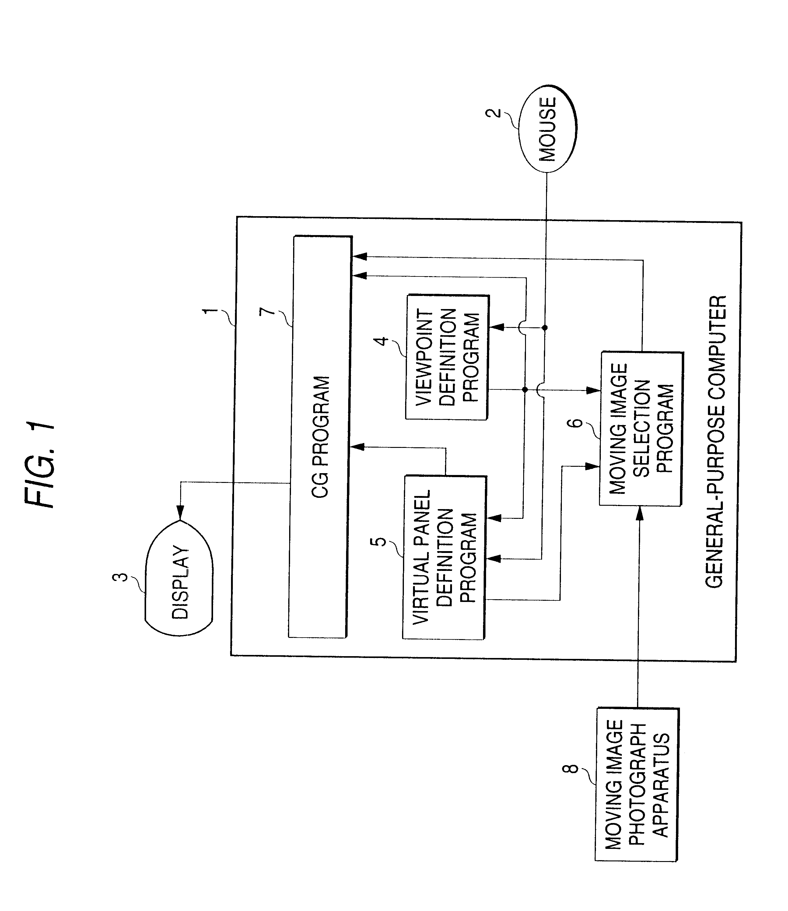
FIG. 13 is a block diagram to show the configuration of an image generation system according to the tenth embodiment of the invention. The image generation system comprises various programs, a general-purpose computer 1 where the programs operate, peripheral machines of a mouse 2 and a display 3, and a three-dimensional graphics board 15 which is installed in the general-purpose computer 1 and can generate a moving image of a virtual object made up of polygons exceeding several tens of thousands of polygons at high speed. The three-dimensional graphics board 15 corresponds to a moving image output apparatus. A viewpoint definition program 4 corresponds to viewpoint definit...

eleventh embodiment

In the above-described embodiments, the virtual panel is one rectangular polygon, but may be of any other shape or may be provided by combining two or more polygons. For example, the virtual panel may be made elliptical for applying a three-dimensional appearance to the virtual panel.

twelfth embodiment

In the above-described embodiments, the moving image photograph apparatus 8 in FIG. 3 photographs a subject through a small hole made in the wall, but may photograph a subject in another way. For example, the subject may be photographed from above the subject, as shown in FIG. 11.


PUM


Abstract

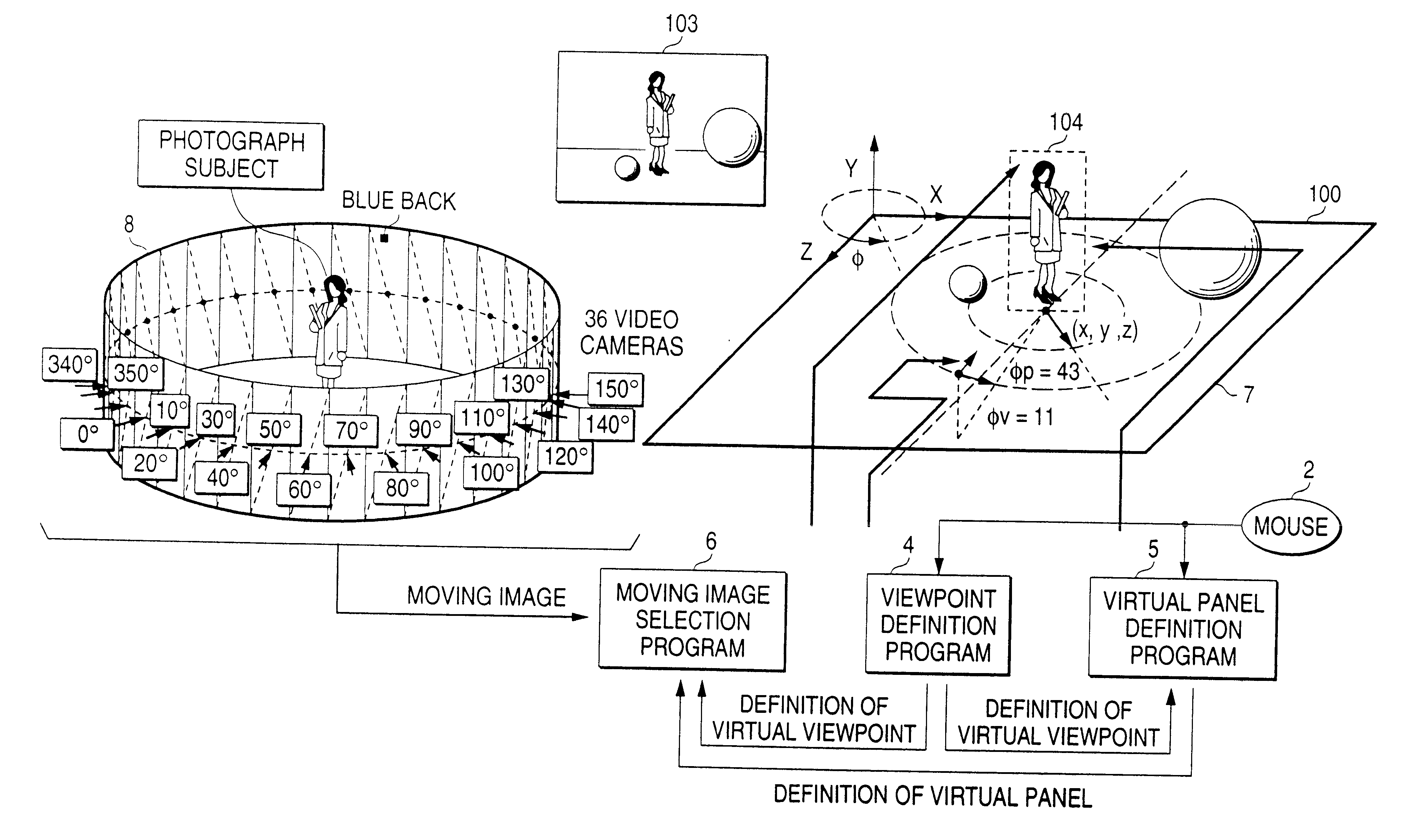
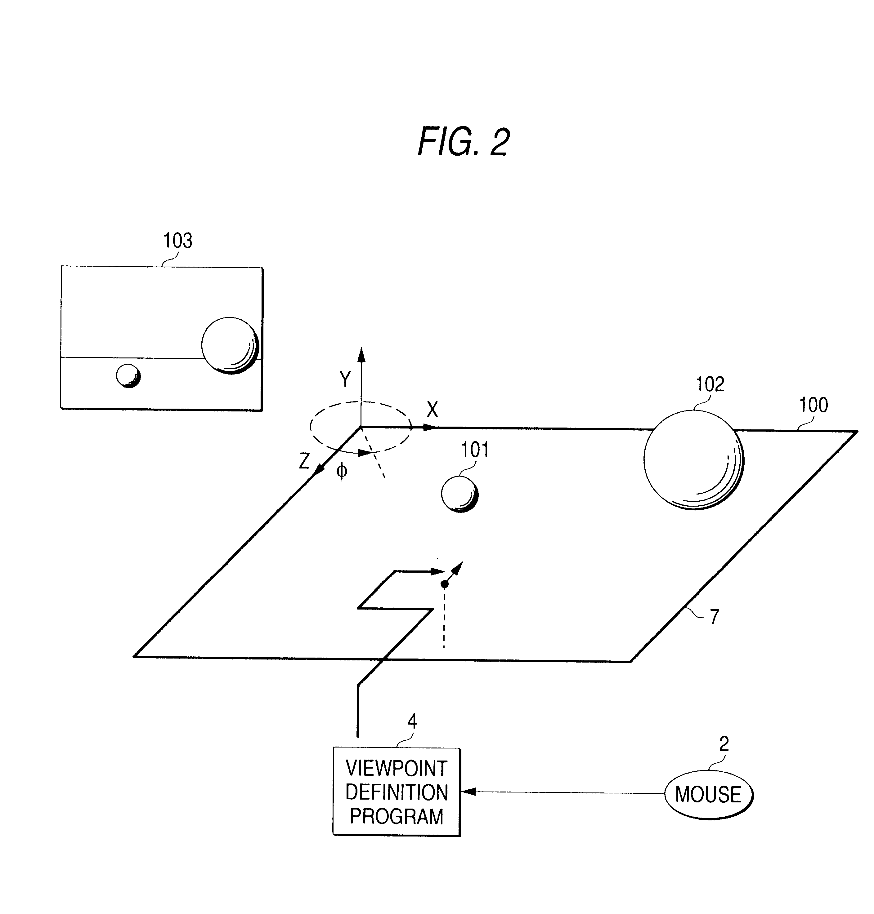
An image generation system which comprises an image generation apparatus having viewpoint definition means for defining a virtual viewpoint placed in virtual three dimensions, virtual panel definition means for defining a virtual object displayed in the virtual three dimensions and defining a virtual panel being placed in the virtual three dimensions, the virtual panel onto which a moving image is projected, based on the virtual viewpoint and the virtual object, moving image selection means for selecting a moving image to be projected onto the virtual panel from among a plurality of moving images based on the virtual viewpoint defined in the viewpoint definition means, and virtual three-dimensional image generation means for placing the virtual panel defined in the virtual panel definition means in the virtual three dimensions, projecting the moving image selected by the moving image selection means onto the virtual panel, and generating an image from the virtual viewpoint defined in the viewpoint definition means, and a moving image output apparatus for outputting the plurality of moving images to the image generation apparatus.

Description

1. Field of the InventionThis invention relates to an image generation system for generating a virtual three-dimensional image based on computer graphics, an image display system for displaying the image generated in the image generation system, a computer-readable record medium recording an image generation program for generating the image, and an image generation method for generating the image.2. Description of the Related ArtIn computer graphics, particularly, in real-time computer graphics (or real-time CG) for enabling the operator to move the viewpoint freely and smoothly as he or she intends, a method of really representing an object such as a human being having curved surface portions and motion is demanded. A virtual object in the real-time CG is displayed by combining plane polygons called polygons three-dimensionally and giving color to or putting a photo on the polygons. Motion can be given to the virtual object by changing the geometric shape and position of each polyg...

Claims


Application Information

Patent Timeline
Patent Type & Authority Patents(United States)
IPC IPC(8): G06T15/20G06T15/10G06T15/70G06T13/20H04N5/262G06T19/00
CPCG06T15/205G06T13/00
Inventor MAEHARA, HIDEAKITANAKA, SATOSHI
Owner MITSUBISHI ELECTRIC CORP
Learn More