Drum type washing machine

a drum type and washing machine technology, applied in the direction of washing machines with receptacles, other washing machines, textiles and paper, etc., can solve the problems of increasing manufacturing costs, transmission belt slippage such as the belt swinging, driving and driven pulleys and transmission belts producing vibration or oscillation

Inactive Publication Date: 2003-05-20
KK TOSHIBA
View PDF25 Cites 89 Cited by
  • Summary
  • Abstract
  • Description
  • Claims
  • Application Information

AI Technical Summary

Benefits of technology

According to the above-described construction, the depth of a portion of the cabinet on which the motor is not disposed can be prevented from being increased while a space for the motor is ensured between the rear wall of the water tub and the cabinet. Further, breakage of the motor can be prevented or at least restrained even if the water tub swings.
The hole is preferably provided with a louver. Consequently, water or foreign matters can be prevented from entering the cabinet through the hole, and an amount of noise produced by the motor and leaking from the hole can be reduced.

Problems solved by technology

However, provision of the above-described belt transmission mechanism including the driving and driven pulleys and the transmission belt complicates the construction of the washing machine and accordingly increases a manufacturing cost.
Further, the driving and driven pulleys and the transmission belt produce vibration or oscillation during transmission of the motor torque.
A high speed rotation of the motor particularly causes the transmission belt to slip such that the belt swings.
The swinging of the belt increases an amount of vibration produced in the belt transmission mechanism, resulting in production of loud noise.
This requires a large space in the rear of the wash tub and accordingly increases a depth of the cabinet.
Accordingly, when the depth of the cabinet is increased as described above, the standardized waterproof pans cannot be used.

Method used


Image

  • Drum type washing machine
  • Drum type washing machine
  • Drum type washing machine

Examples


first embodiment

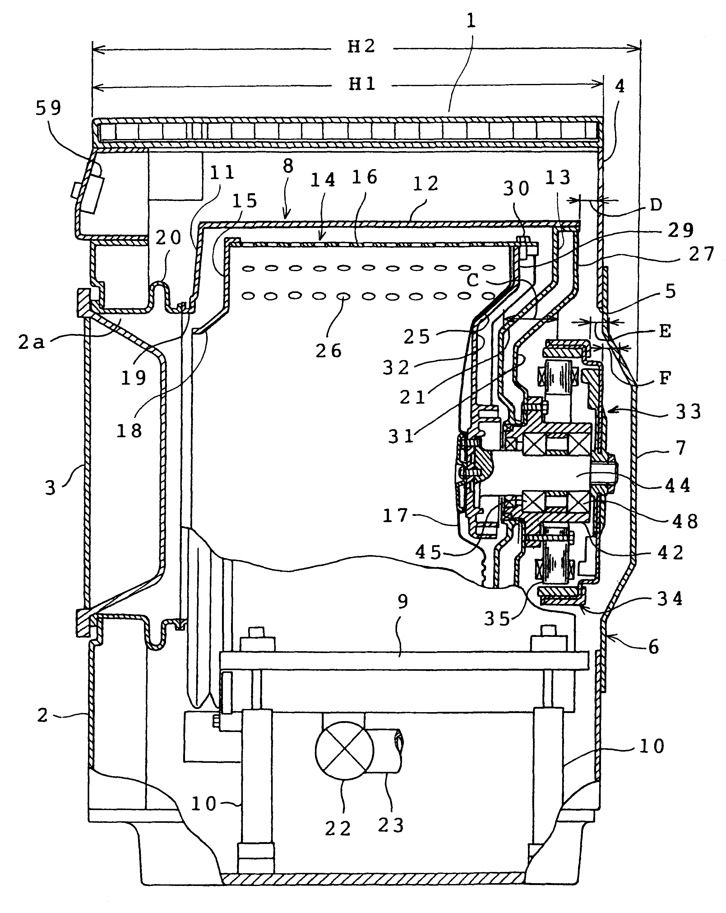
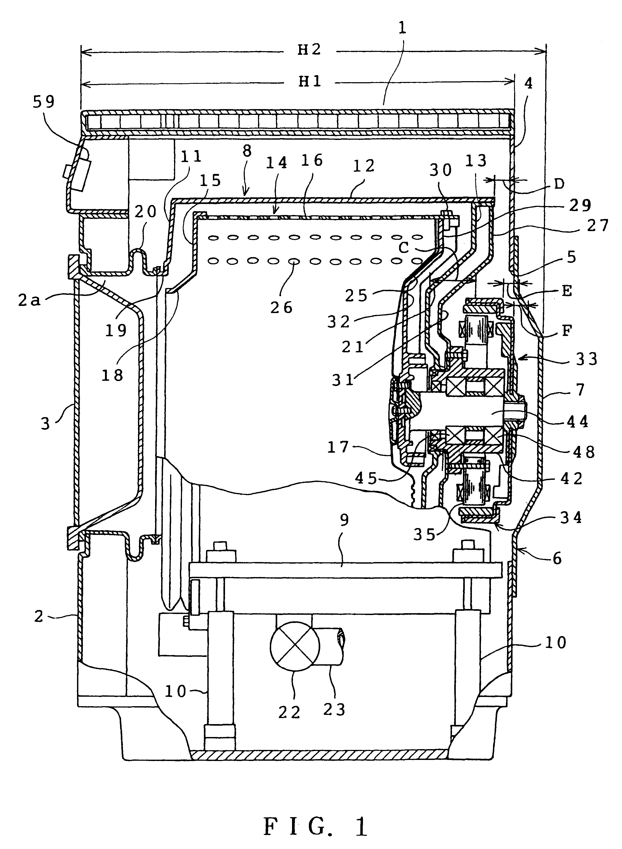
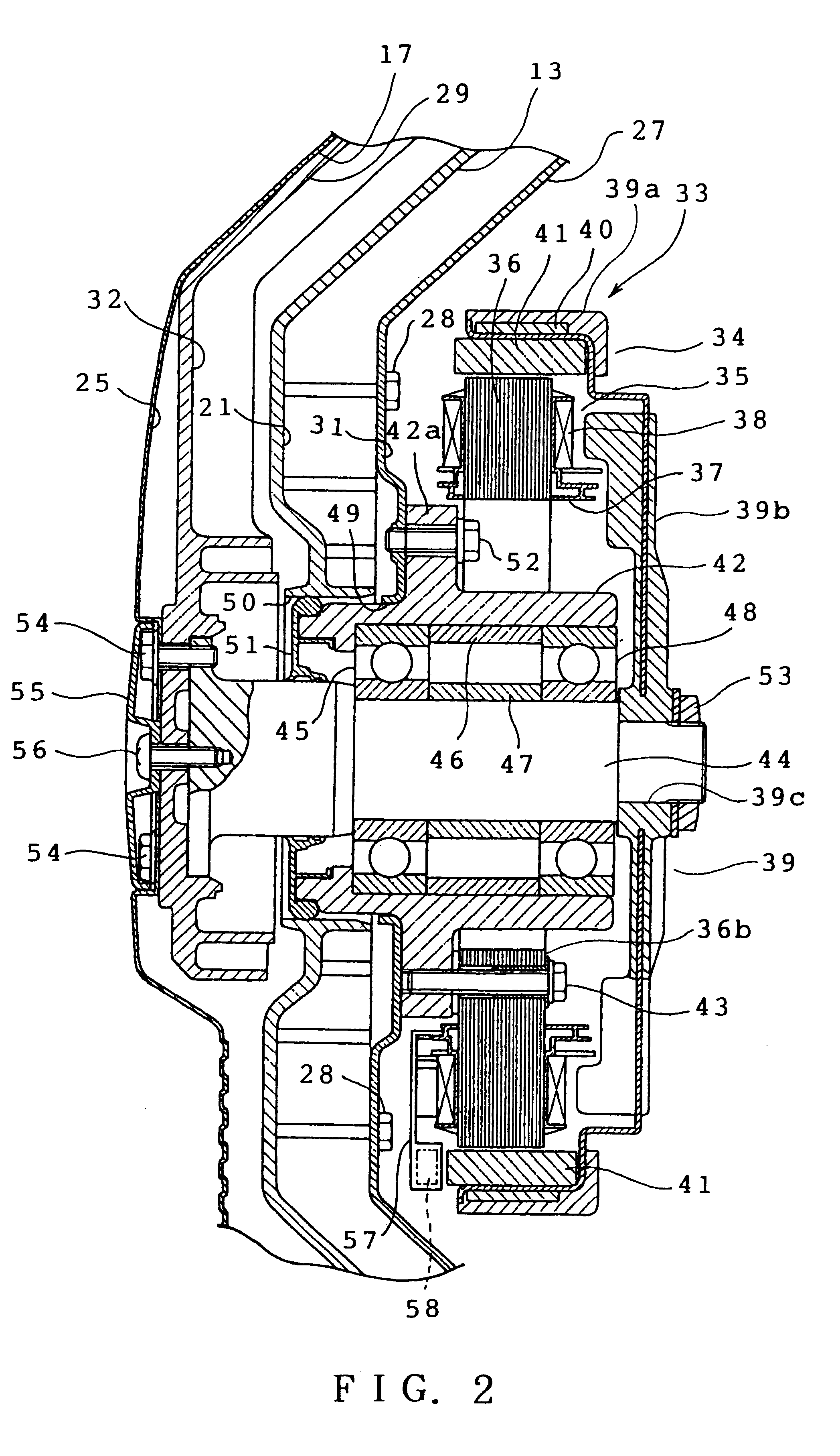
the present invention will be described with reference to FIGS. 1 to 3. Referring to FIG. 1, a drum type washing machine of the first, embodiment in accordance with the invention is shown. The washing machine comprises an outer cabinet 1 formed into the shape of a generally rectangular box. The cabinet 1 includes a front wall 2 having a substantially central access hole 2a through which laundry is put into and taken out of a rotating tub 14. A door 3 is mounted on the front wall 2 to close and open the access hole 2a. The cabinet 1 further includes a rear wall 4 having a substantially central working hole 5. A back panel 6 is detachably mounted on the rear wall 4 by screws (not shown) so as to close the working hole 5. The back panel 6 includes a rearwardly extruding convexity 7 formed by pressing the back panel 6 except its peripheral portion serving as a mounting portion to the rear wall 4. A peripheral dimension of the convexity 7 is gradually decreased rearward.

A drum-shaped wat...


PUM


Abstract

A drum type washing machine includes an outer cabinet having a rear wall, a water tub elastically mounted in the cabinet and having a rear wall, a drum type rotating tub provided in the water tub so as to be rotatable about a horizontal axis, and an electric motor provided on the rear wall of the water tub to directly drive the rotating tub. A distance between a portion of the rear wall of the water tub on which the motor is provided and the rear wall of the cabinet is larger than a distance between a distance between another portion of the rear wall of the water tub and the rear wall of the cabinet.

Description

1. Field of the InventionThis invention relates generally to a drum type washing machine provided with a rotating tub rotatable about a horizontal axis, and more particularly to such a drum type washing machine in which the rotating tub is directly rotated by an electric motor.2. Description of the Prior ArtThere have conventionally been provided drum type washing machines comprising an outer cabinet, a water tub elastically mounted on a plurality of suspension mechanisms in the cabinet, and a rotating tub mounted in the water tub so as to be rotatable about a horizontal axis. Bearings are provided in the rear of the water tub to support a shaft of the rotating tub. The shaft has a rear end on which a driven pulley is mounted. An electric motor is disposed below the water tub and has a shaft on which a driving pulley is mounted. A transmission belt extends between the driving and driven pulleys. Upon rotation of the shaft of the motor, torque is transmitted through the driving pulle...

Claims


Application Information

Patent Timeline
Patent Type & Authority Patents(United States)
IPC IPC(8): D06F37/42D06F23/06D06F25/00D06F37/22D06F37/00D06F23/00D06F37/20D06F37/30
CPCD06F23/06D06F25/00D06F37/42D06F37/22D06F37/304D06F37/20H02K9/06
Inventor ITO, MASUMIYAMAZAKI, FUMITAKAKAWABATA, SHINICHIROSASANO, KIYOMIHASHIBA, SHUJI
Owner KK TOSHIBA
Why Eureka
Try Eureka