Apparatus for mounting a cutting strip

a technology for mounting accessories and cutting strips, applied in the direction of lamination, paper/cardboard containers, containers, etc., can solve the problem of not being used

Inactive Publication Date: 2003-05-27
CARTON EDGE SYST
View PDF35 Cites 16 Cited by
  • Summary
  • Abstract
  • Description
  • Claims
  • Application Information

AI Technical Summary

Problems solved by technology

This arrangement is convenient where the cutting strip is to be placed onto the blank adjacent a fold line in the blank, but clearly cannot be used where the cutting strip is to be mounted overlapping a free edge of the blank.

Method used


Image

  • Apparatus for mounting a cutting strip
  • Apparatus for mounting a cutting strip
  • Apparatus for mounting a cutting strip

Examples


Embodiment Construction

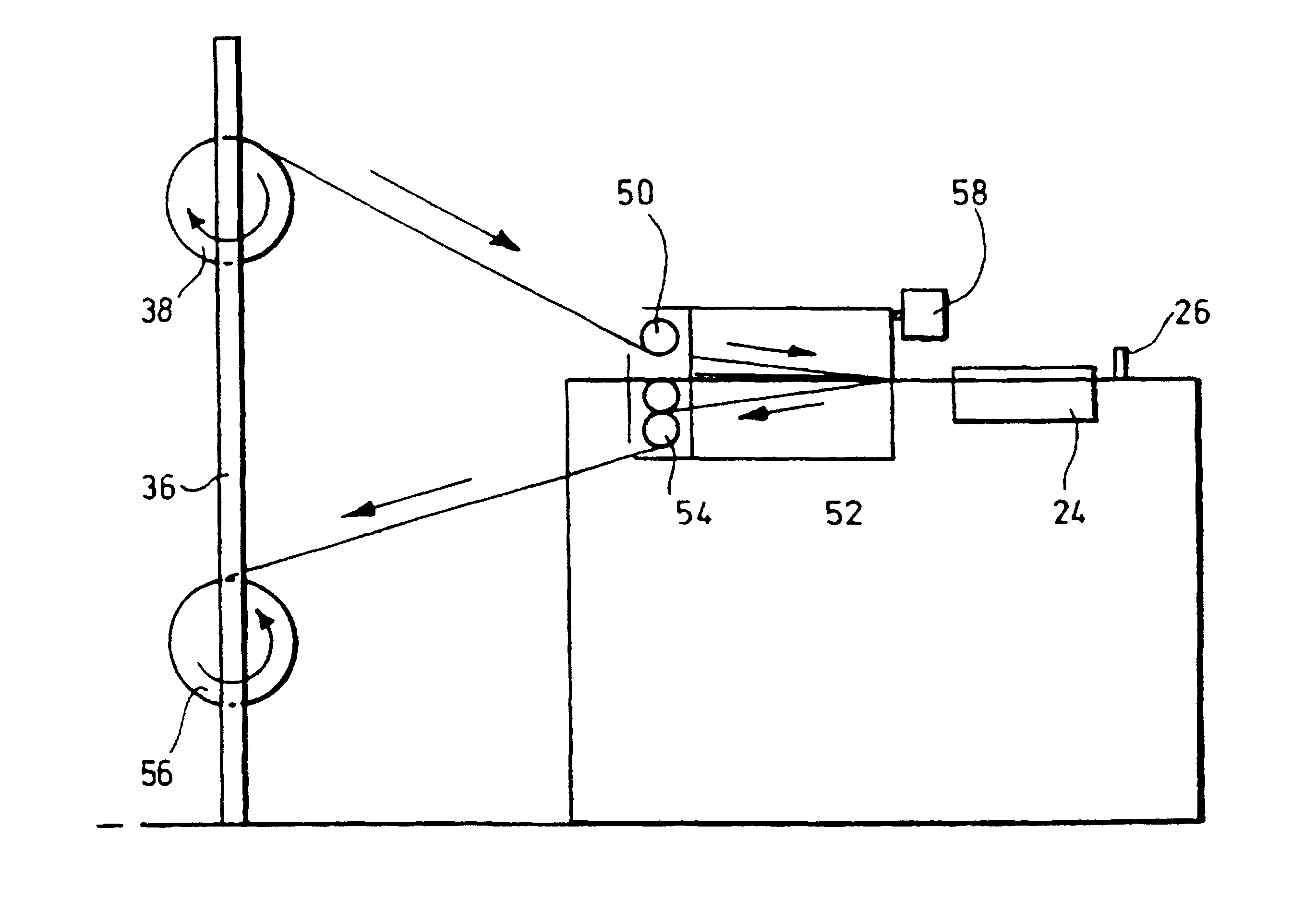
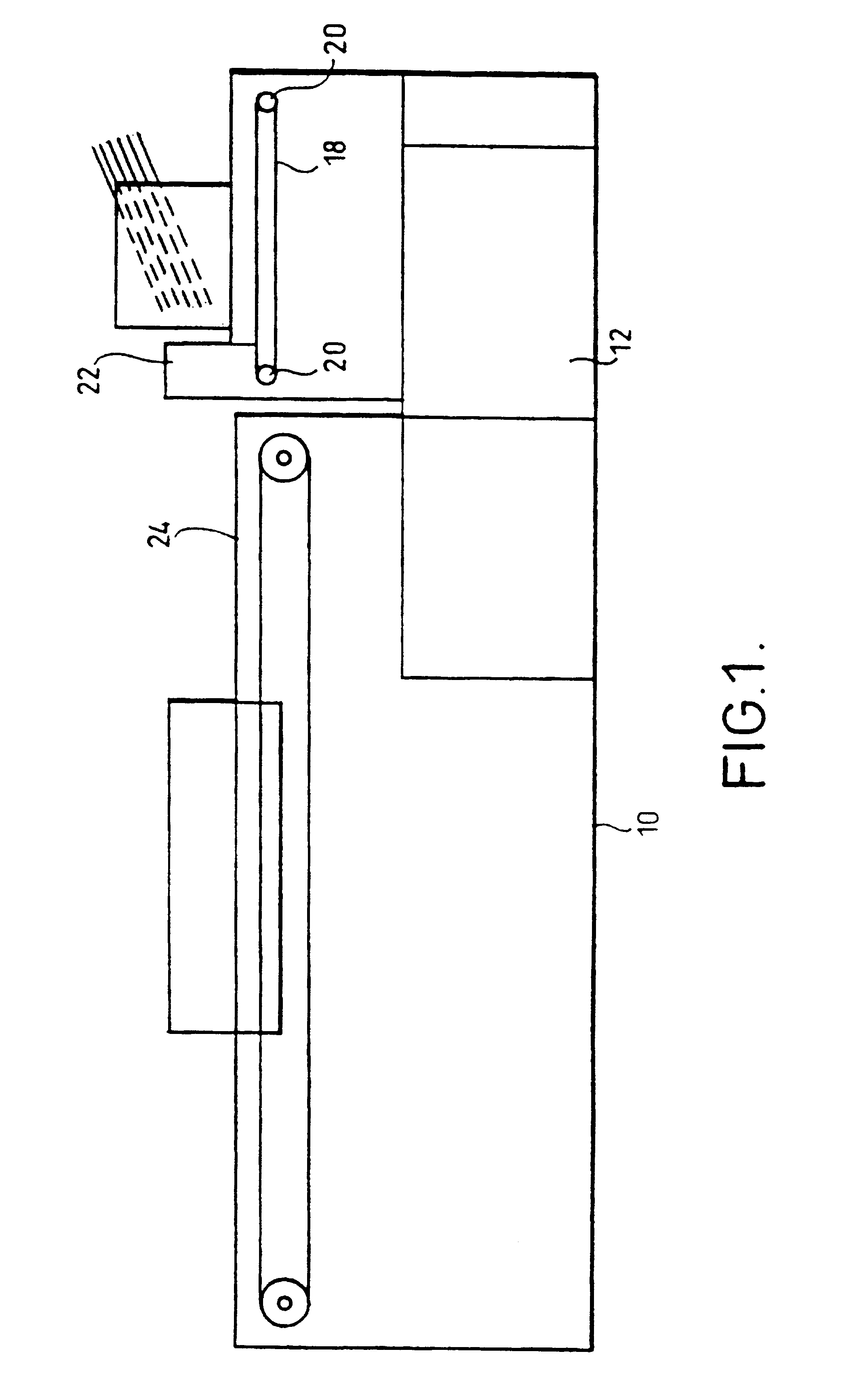
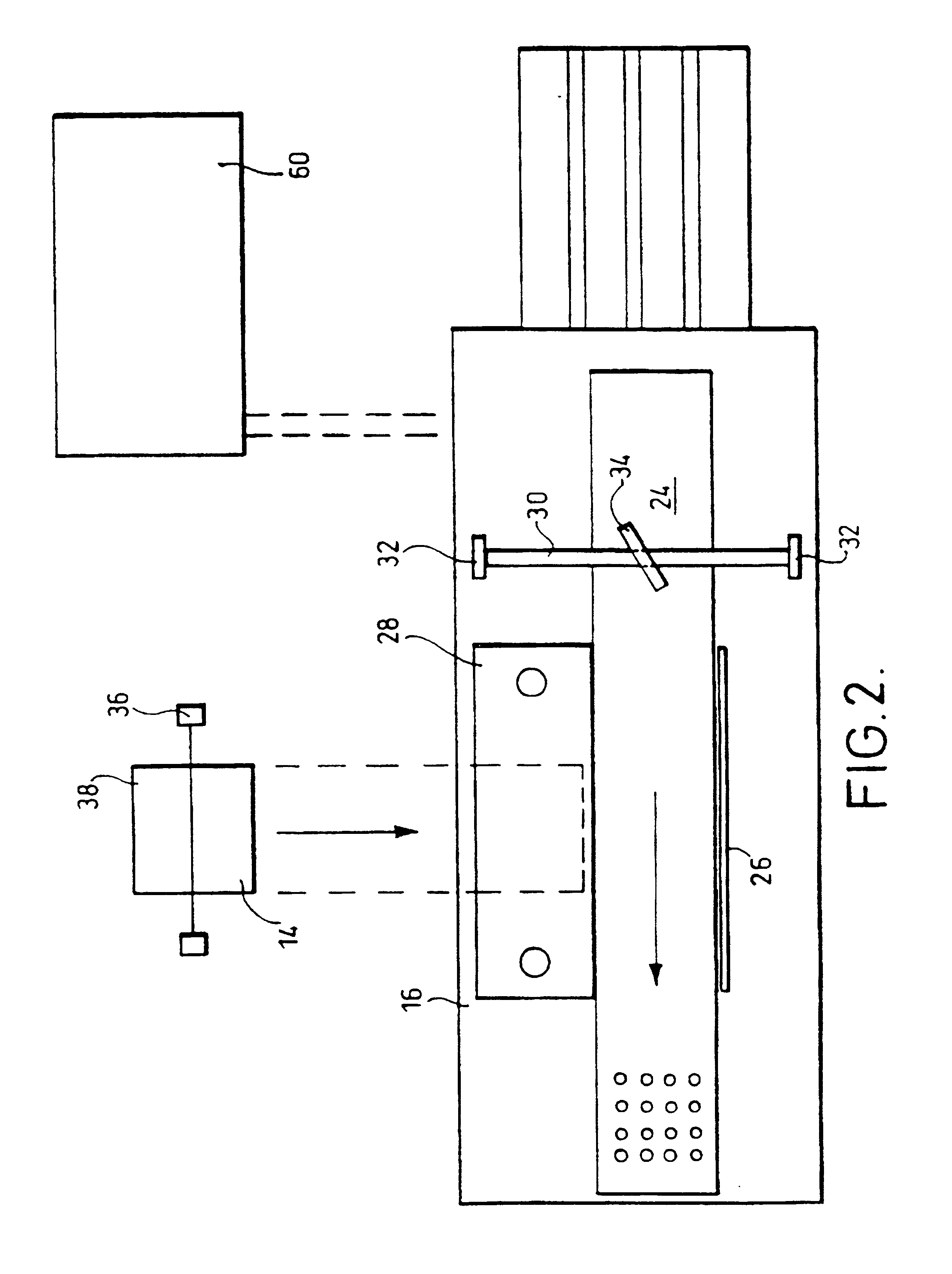
The apparatus 10 of the embodiment of the invention comprises a carton blank feeder unit 12 and a cutting strip material feed unit 14 both leading to a cutting strip application station 16.

The carton blank feeder unit 12 comprises a conveyor belt 18 on two rollers 20. An upright feed gate 22 is provided over the belt 18 in front of the front roller 20. Side walls are provided to either side of the feed gate 22 and the feed gate is adjustable upwards and downwards with respect to the side walls. Carton blanks are placed in a stack on the feeder unit behind the feed gate 22 and the feed gate is raised to an appropriate height to allow only the bottom carton blank of the stack to be conveyed by the conveyor belt 18 under the feed gate and onto the cutting strip application station 16. The conveyor belt 18 feeds the carton blank onto a main conveyor belt 24. The main conveyor belt 24 is run at a higher speed than the conveyor belt 18 so that a gap is provided between successive carton b...


PUM

PropertyMeasurementUnit
pressureaaaaaaaaaa
suctionaaaaaaaaaa
widthaaaaaaaaaa

Abstract

This invention provides an apparatus for attaching a cutting strip to a carton blank. The apparatus includes a first member for conveying carton blanks past a second member, and the second member is arranged to cut a cuffing strip from a supply of cuffing strip material and deposit the cutting strip upon a carton blank. The first member may be a conveyor belt fitted with a suction member, and the second member may be upper and lower dies that are movable relative to one another and a member that can feed a supply of cutting strip material between the dies. Initial downward movement of the upper die cuts a cutting strip from the supply of cutting strip material and the cutting strip is retained on the upper die. Further downward movement of the upper die brings the cutting strip into contact with a carton blank. The apparatus may also include an alignment member to ensure that the carton blanks are properly positioned relative to the second member when the cutting strips are attached.

Description

1. Field of the InventionThe invention relates to apparatus for mounting a cutting strip.2. Description of the Related ArtIt is known to mount a metal cutting strip on a carton for cling film so that cling film withdrawn from the carton can be cut on the metal cutting strip. The metal strip may be applied by a machine in which metal sheet from a roll is advanced by passing between driven rollers. The sheet enters a guide which directs the sheet between a fixed lower die and a movable upper die. When the upper die has cut a strip from the sheet, the strip is held onto the die by suction and is carried down onto a carton blank. At the same time as cutting the strip, the strip is perforated by downward pegs which leave downwardly extending teeth around each perforation. The pressure of the upper die forces the teeth into the carton to mechanically fix the metal strip to the carton. The carton blank is brought up to the die and stopped for the cutting strip to be mounted. The conveyor b...

Claims


Application Information

Patent Timeline
Patent Type & Authority Patents(United States)
IPC IPC(8): B31B1/90B31B1/74
CPCB31B1/90B31B2201/9004Y10T156/1378Y10T156/1054Y10T156/1339Y10T156/107Y10T156/1768Y10T156/1313Y10T156/1326Y10T156/1335B31B50/00B31B50/811
Inventor OWEN, EDWIN WYNJAMIE, IAN
Owner CARTON EDGE SYST
Why Eureka
Try Eureka