Door lock with roller catch, especially for motor vehicles

a technology of roller catch and door lock, which is applied in the field of door locks, can solve the problems of high requirements for sensors, difficult and expensive manufacture of sensors with such high requirements, and the movement of roller catch back and forth

Inactive Publication Date: 2003-05-27
HUF HULSBECK & FURST GMBH & CO KG
View PDF11 Cites 34 Cited by
  • Summary
  • Abstract
  • Description
  • Claims
  • Application Information

AI Technical Summary

Problems solved by technology

The known door lock requires a lot of space.
During closing of the aforementioned door gap disruptions may result, for example, by an obstacle which projects into the door gap.
Even the effect of the elastic door sea

Method used


Image

  • Door lock with roller catch, especially for motor vehicles
  • Door lock with roller catch, especially for motor vehicles
  • Door lock with roller catch, especially for motor vehicles

Examples


Embodiment Construction

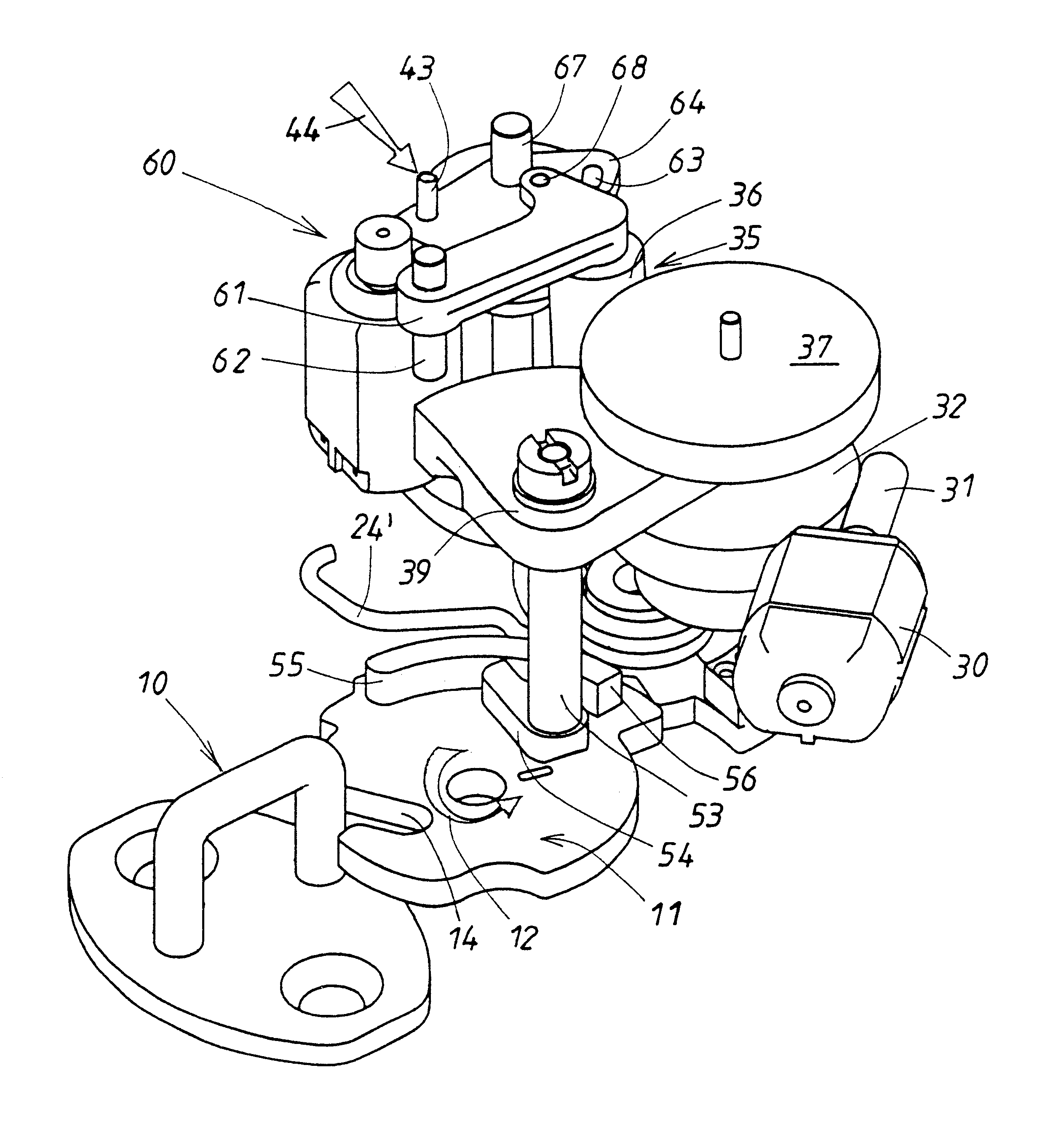
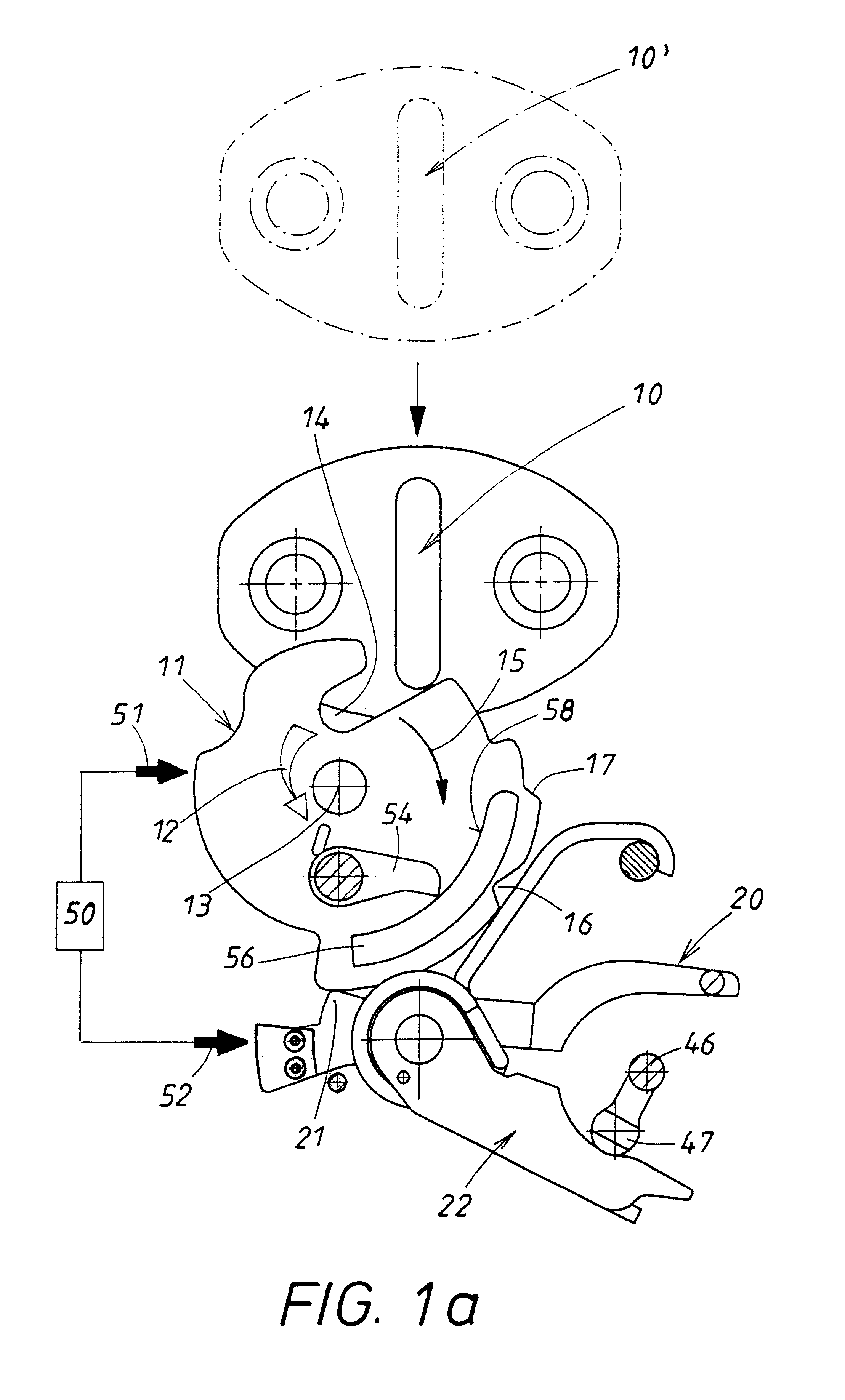
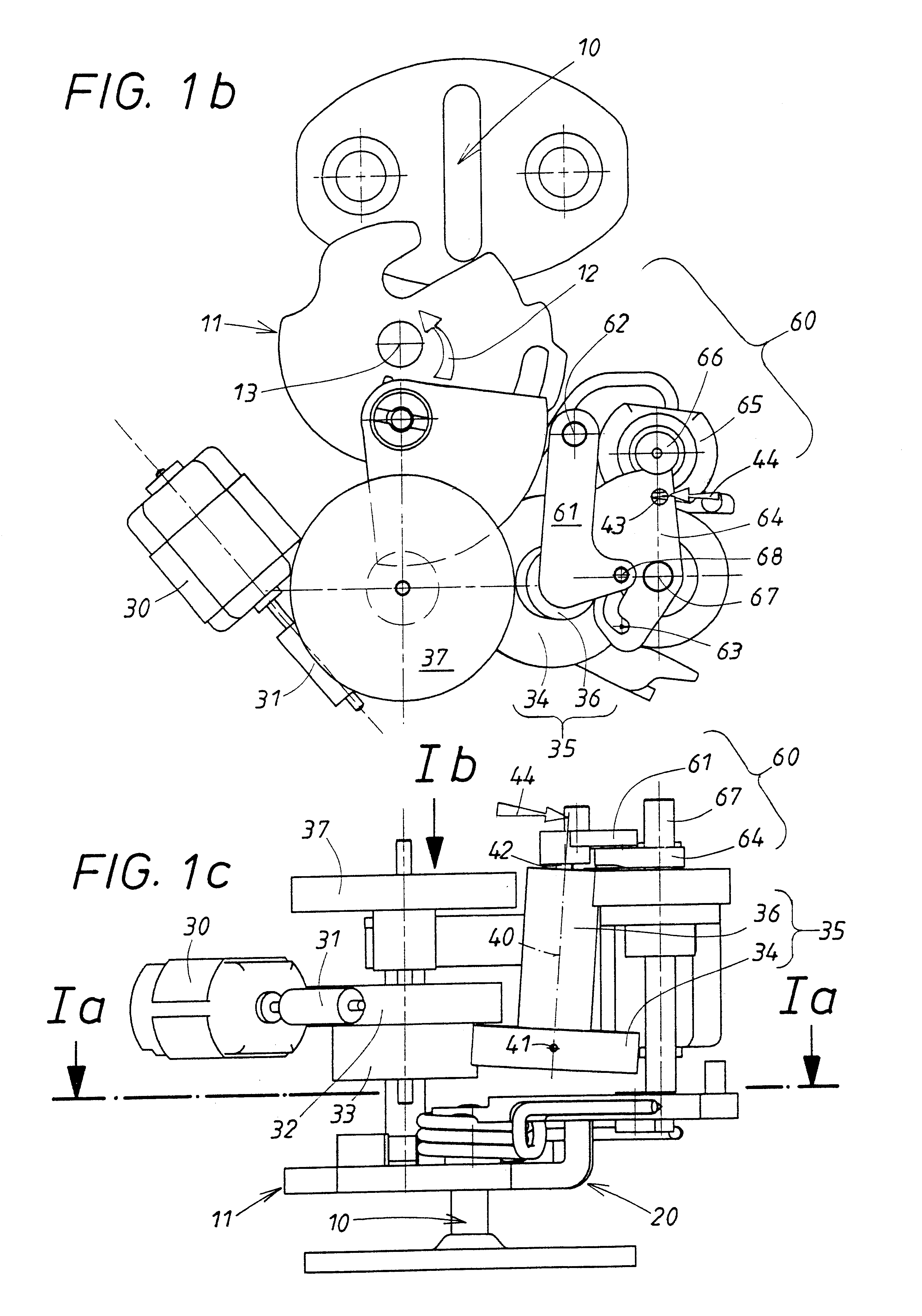
The configuration of the lock is explained in more detail with the aid of FIGS. 1a to 1d. The door lock comprises a roller catch 11 which is subjected to a restoring force, illustrated by the force arrow 12, of a spring, not shown in detail. The roller catch 11 is pivotably supported on a bearing pin 15 in a housing, not shown in detail, and is usually fastened on the door, not shown in detail. Instead of a side door, another type of door, for example, the rear hatch of a motor vehicle, could be concerned. The roller catch 11 comprises a slot-shaped receiving device 14 for a locking part 10 which is bracket-shaped in this embodiment. When the locking part is removed from the roller catch 11, as illustrated at 10' in FIG. 1a, it is maintained by its spring-load 12 and rotary stops, not illustrated in detail, in an open position illustrated in FIG. 1a. In this connection, the roller catch 11 with its receiving device 14 remains accessible from the exterior. The locking part 10 is usua...


PUM


Abstract

The invention relates to a door lock provided with a roller catch (11). When the door is closed an immobile locking part (10) moves into said roller catch (11), causing it to pivot from an open position into a preliminary or main latching position, the roller catch (11) being held by a latch. For greater user comfort and a more compact door lock the invention provides for the same drive motor (30) to be used as locking aid and as opening aid. A transmission element (35) which can be moved into two different positions is introduced into the gear assembly (31, 37). The drive energy generated by the drive motor (30) is transmitted in one position to the roller catch and in the other position to a second output track leading to the locking latch (20).

Description

1. Field of the InventionThe invention relates to a door lock wherein the roller catch comprises in addition to the pre-catch also a main catch into which the pawl drops. Sometimes a gap remains when closing an open door because the pawl reaches only the pre-catch of the roller catch. This means that the roller catch remains in its pre-catch position. In order to be.able to close the gap, the auxiliary motor means are provided which engage the roller catch. They have the task to further move the roller catch into its final position in which the pawl drops into the main catch. In the following, this final position will be referred to as "main catch position". The door gap is now closed.2. Description of the Related ArtIn a known door lock (DE 195 33 196 A1) two drive motors cooperate via two gears with a pivotable carousel support on which the pawl is positioned. One motor serves as a closing aid and the other motor as an opening aid. During closing, the pawl is pushed away by a pre-...

Claims


Application Information

Patent Timeline
IPC IPC(8): E05B65/12E05B17/00E05B47/00E05B47/02E05B81/14
CPCE05B81/14Y10S292/23Y10T292/1047Y10T292/1082E05B17/00E05B47/02
Inventor SZABLEWSKI, PIOTR
Owner HUF HULSBECK & FURST GMBH & CO KG
Why Eureka
Try Eureka