Lamp grounding and leakage current detection system

a leakage current detection and grounding technology, applied in the direction of electric variable regulation, process and machine control, instruments, etc., can solve the problems that the current feedback loop of the current subsystem cannot detect the leakage current developed within the lamp, and the controller cannot regulate the lamp based on the current feedback loop

Inactive Publication Date: 2003-05-27
O2 MICRO INT LTD
View PDF103 Cites 141 Cited by
  • Summary
  • Abstract
  • Description
  • Claims
  • Application Information

AI Technical Summary

Problems solved by technology

However, the drawback to using virtual grounding techniques is that the leakage current developed within the lamp cannot be detected through the current feedback loop across R.sub.s.
Thus, the controller cannot regulate the lamp based on the total current that includes the leakage current, since this current is lost to ground.

Method used


Image

  • Lamp grounding and leakage current detection system
  • Lamp grounding and leakage current detection system
  • Lamp grounding and leakage current detection system

Examples


Embodiment Construction

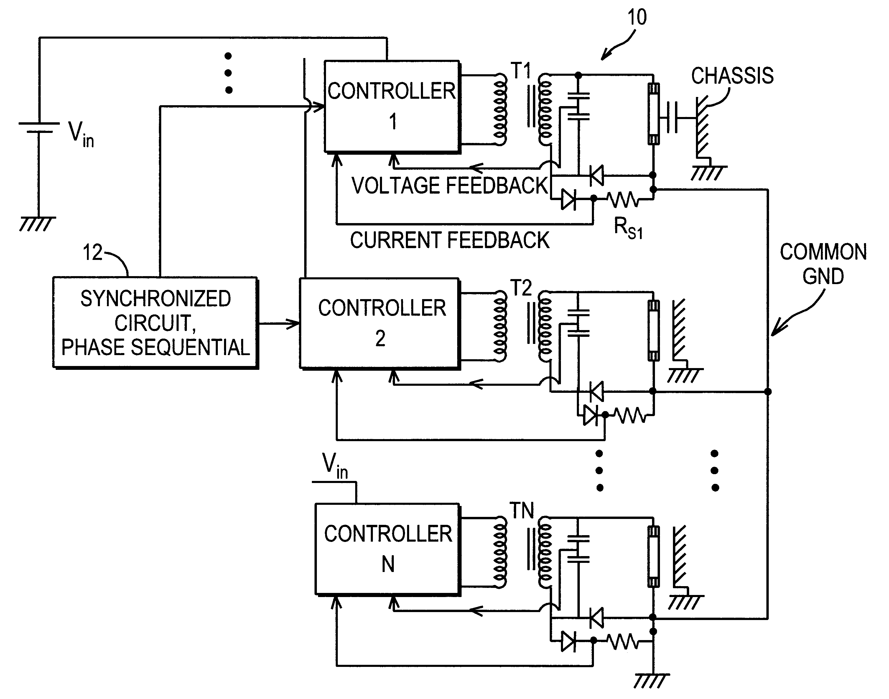
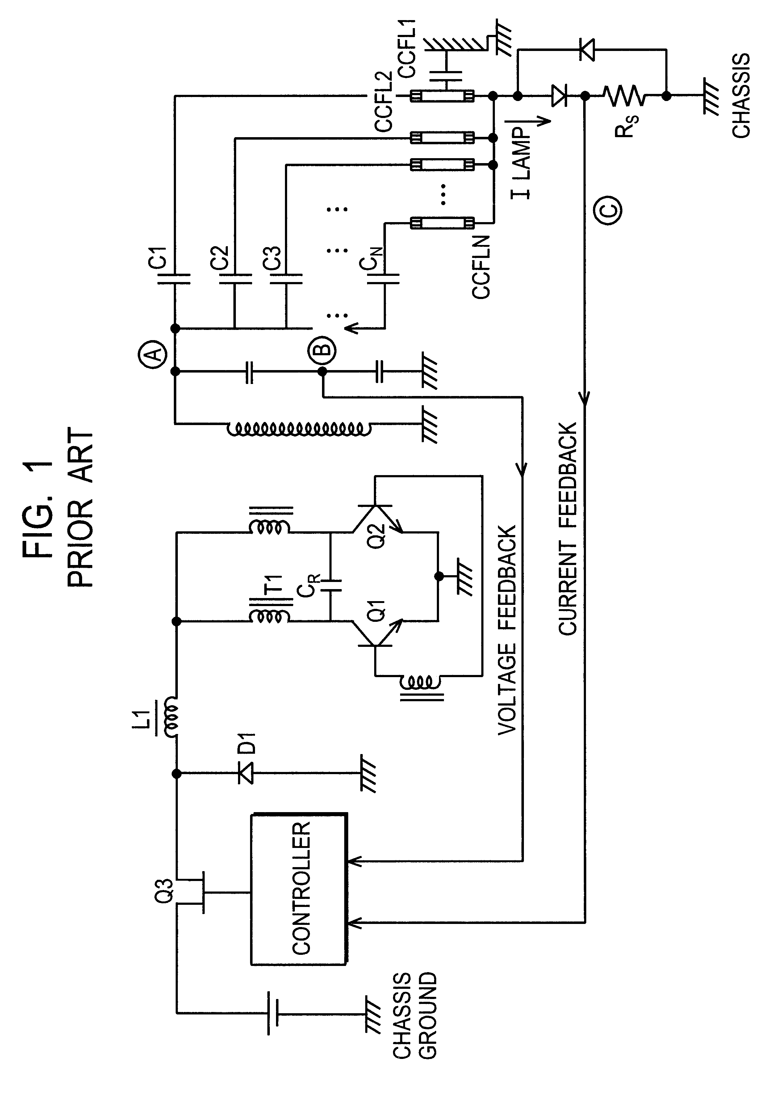
FIG. 3 depicts a lamp controlling system 10 according to one exemplary embodiment of the present invention. In the exemplary embodiment of FIG. 3 a plurality of controllers Controller 1, Controller 2, . . . Controller N are provided for independent control of a plurality of respective lamps Lamp 1, Lamp 2, . . . Lamp N. The specifics of the controller are not important for understanding the present invention, and may be comprised of a push pull-type Royer circuit as disclosed in FIG. 1, a half-bridge inverter, a full-bridge / H-bridge inverter or other inverter topologies known in the art sufficient to drive the transformer T1, T2 . . . TN with an AC signal from the DC voltage V.sub.n. In this exemplary embodiment, each lamp is coupled to the chassis ground via the leakage capacitance C.sub.Lk of the lamp (FIG. 4.) The chassis may comprise a system ground. Voltage feedback and current feedback are provided for controllable operation of the lamp in a manner well understood in the art.

U...


PUM


Abstract

A common ground system and methodology for one or more loads. In exemplary embodiments, a lamp load is regulated by providing a common ground on the secondary side of the transformer and the load. Lamp regulation is provided, in part, via a current feedback loop provided on the secondary side that is commonly grounded between the bottom of the transformer and the bottom of the lamp through the current feedback loop. In this manner, a feedback signal is developed that includes the leakage current of the lamp.

Description

1. Field of the InventionThe present invention relates to grounding techniques and leakage current detection techniques for lamps associated with LCD display panels. Also, this invention relates to the reliable ignition technique for each lamp in a multiple lamp system. In particular, the present invention relates to a common grounding technique utilizing the metallic chassis of the LCD panel to insure that leakage current of individual lamps is detected to provide more accurate current feedback control. Particular utility for the present invention is in LCD display panels with multiple CCFL lamps, although the present invention is equally applicable in single lamp and multiple lamp environments including lamps other than CCFL type.2. Description of Related ArtFIG. 1 depicts a conventional Royer circuit that is used to drive multiple CCFL lamps shown as CCFL1 . . . CCFLN. The operational characteristics of the controller and the Royer Is circuit comprised of switches Q1 and Q2 on th...

Claims


Application Information

Patent Timeline
Patent Type & Authority Patents(United States)
IPC IPC(8): H05B41/285H05B41/28H02M7/5383
CPCH02M7/53835H05B41/2851Y10S315/05
Inventor LIN, YUNG-LIN
Owner O2 MICRO INT LTD
Why Eureka
Try Eureka