Virtual network adapter

a virtual network and adapter technology, applied in the field of virtual network adapters, can solve the problems of limiting the number of devices supported within one network, not allowing the later addition of new devices, and after-market devices typically not supporting advanced applications demanding access to vehicle real-time buses and networks

Inactive Publication Date: 2003-05-27
IBM CORP
View PDF10 Cites 82 Cited by
  • Summary
  • Abstract
  • Description
  • Claims
  • Application Information

AI Technical Summary

Benefits of technology

It is an advantage of the present invention that, although in reality not actively acting on the real-time network, the VNA system is supporting the major bus access functions like

Problems solved by technology

a) The most important factor is safety. Typically providing access to all major Electronic Control Units (ECUs) within the vehicle, safety relevant devices like brake control, engine management and others are connected to the real-time bus-systems;
b) The real-time bus-systems typically provide a limited amount of electrical drive capability, thus limiting the number of devices supported within one network.
c) The number of bus participants and accompanying addresses / message-IDs are kept to a minimum to allow to achieve cost effective systems.
As a consequence to the facts as explained, the busses are not `open to public`, thus do not allow adding on new devices at a later time.
Restricted by the status of bus access capabilities, these after-market devices are typically not supporting advanced applications demanding access to the vehicle real-time buses and networks.
Due to the limiting facts as explained, this type of new services can only be offered by the original manufactures, provided as an OEM device, developed in cooperation with the vehicle developers.
Unless add-on-device bus access capability is not explicitly provided and built in by the vehicle manufacturer, after market devices are not supported and cannot be allowed to be added to the vehicle domain networks in a `plug and play` manner--an important security issue with potential legal consequences if ignored.
Given this typical procedure, as normally executed by standard bus-controllers, therefore, the major requirement of not influencing the network cannot be fulfilled.
As a consequence, not being able to arbitrate and to logically interfere with the respective bus participants, thus not being able to `request` required data on demand, in the `first thought` leads to the conclusion, not providing the network access appropriate to the applications in mind.

Method used


Image

  • Virtual network adapter
  • Virtual network adapter
  • Virtual network adapter

Examples


Embodiment Construction

)

While the present invention will be described more fully hereinafter with reference to the accompanying drawings, in which a preferred embodiment of the present invention is shown, it is to be understood at the outset of the description which follows that persons of skill in the appropriate arts may modify the invention here described while still achieving the favorable results of the invention. Accordingly, the description which follows is to be understood as being a broad, teaching disclosure directed to persons of skill in the appropriate arts, and not as limiting upon the present invention.

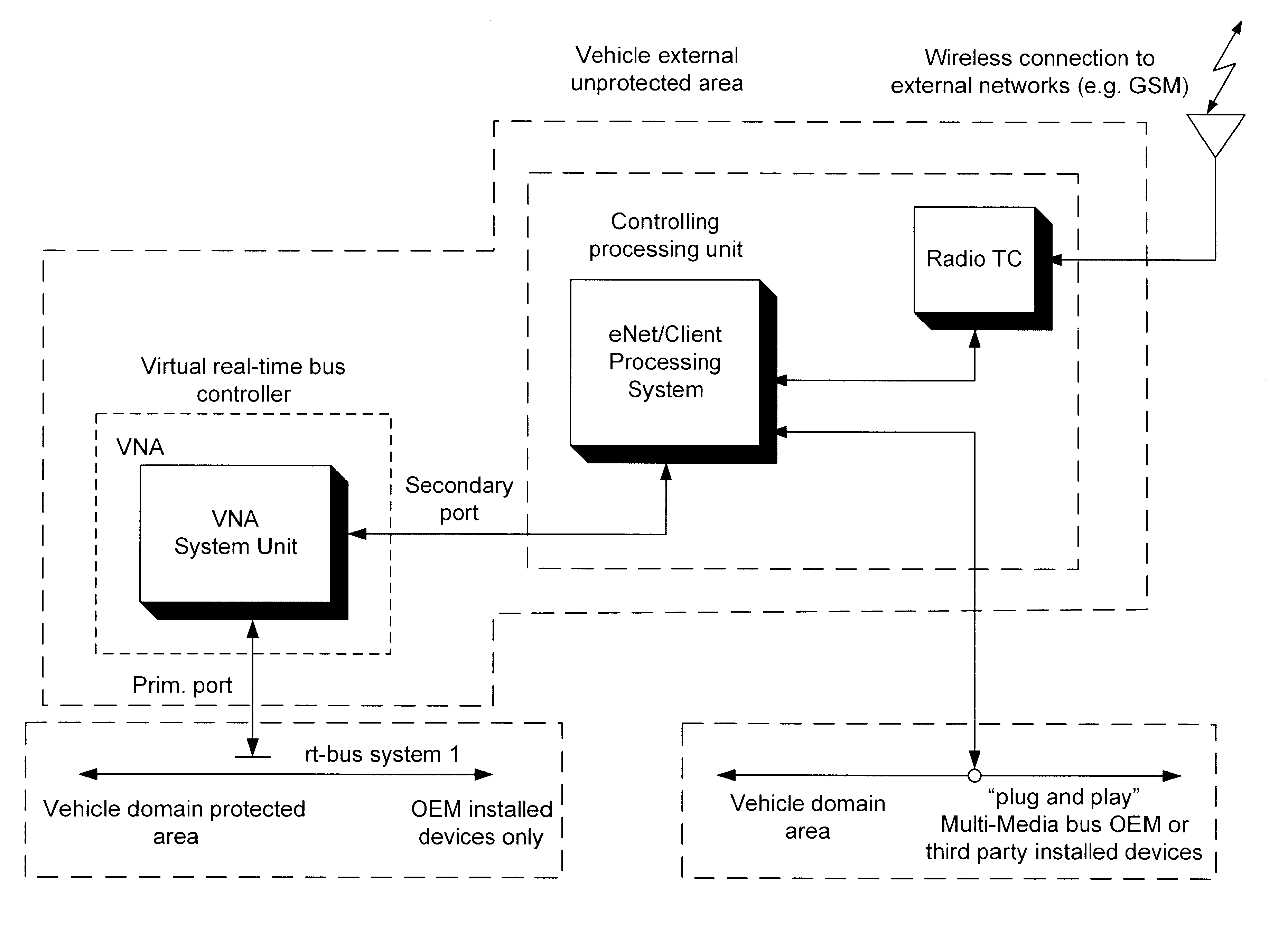
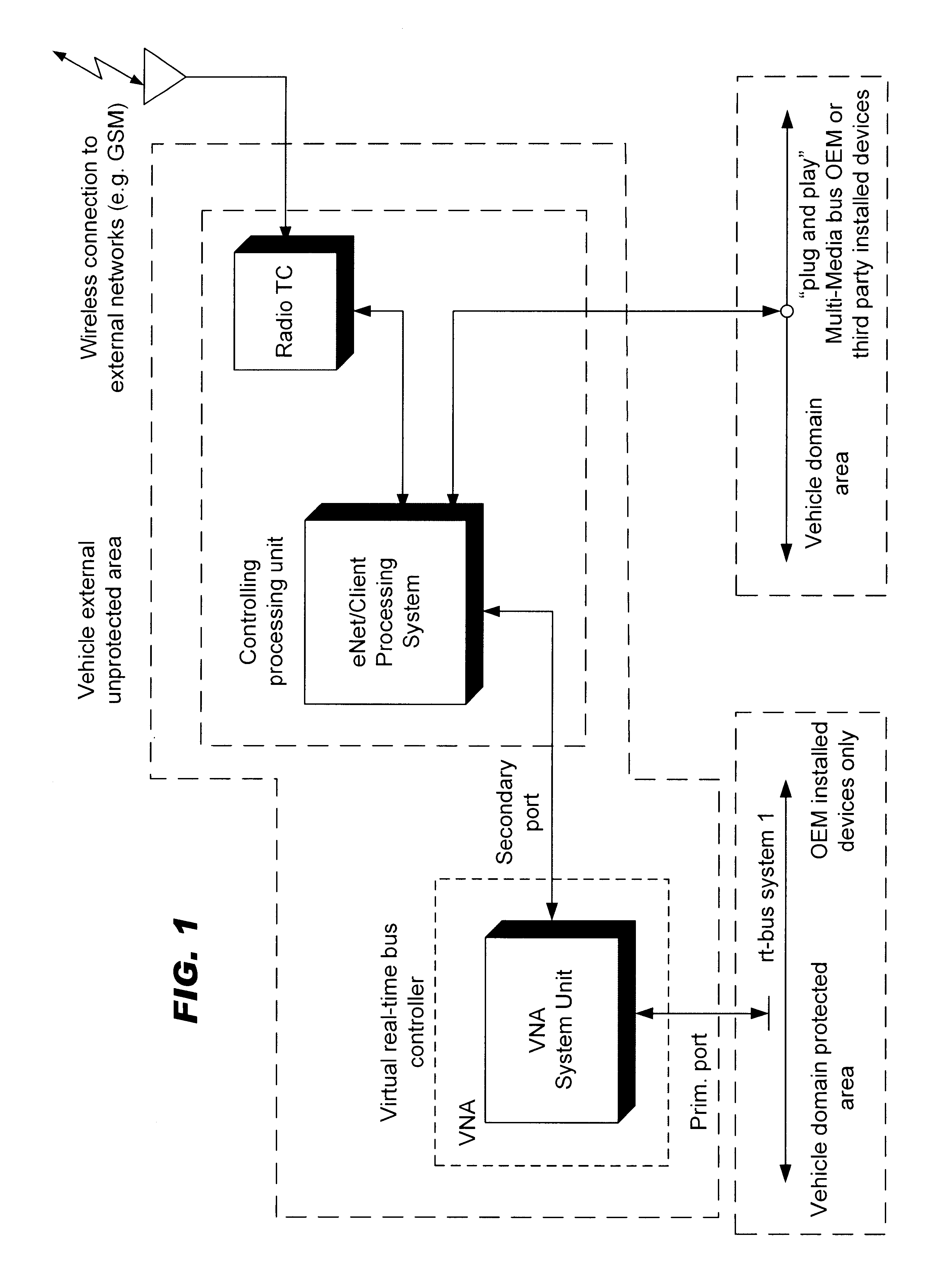
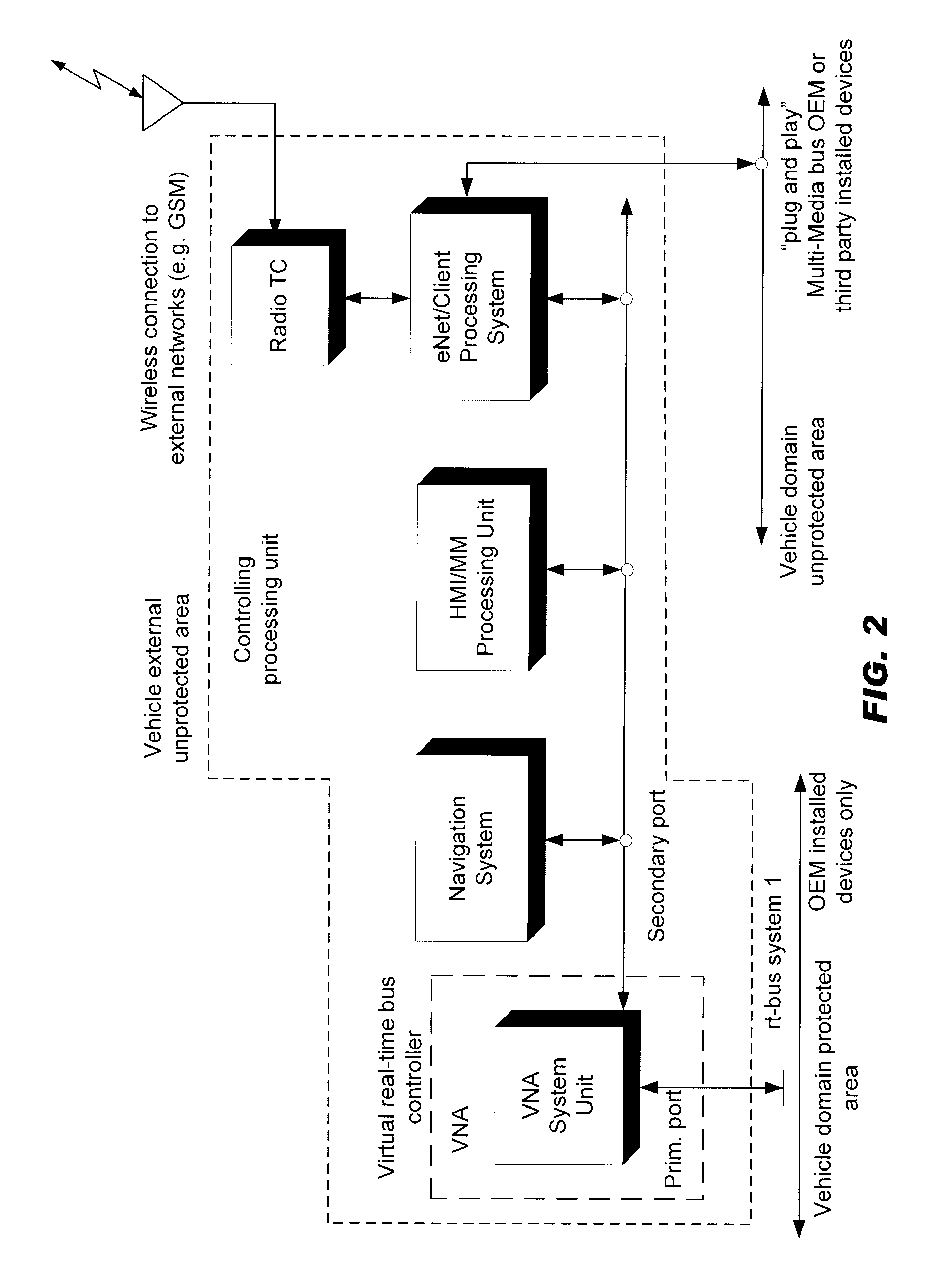
The idea of the VNA is to take leverage of the prior explained conditions and constellation. Using a bus monitor method, not influencing the network (insignificant surge of energy), the VNA will acquire all messages present at the network. The internal processes are designed to identify the messages and to apply programmable filtering algorithms, thus reducing the amount of data and messages,...


PUM


Abstract

A method and an electronic circuit arrangement is provided which allows observation of bus-systems and networks. In particular the method and circuit arrangement does not cause electrical or physical constraints and influence to the bus-systems and networks. Still more specifically it provides for accessing static bus-systems and networks in particular used by real-time constrained systems and applications such as in automotive vehicles.

Description

FIELD AND BACKGROUND OF THE INVENTIONThe present invention relates to a method and an electronic circuit arrangement allowing observation of bus-systems and networks. In particular the invention relates to such a method and circuit arrangement not causing electrical or physical constraints and influence to the bus-systems and networks. Still more specifically the invention provides for accessing static bus-systems and networks in particular used by real-time constrained systems and applications.Buses and networks, used to interconnect real-time electronic systems, are typically defined during system definition and design. The number of bus attachments (loads) and, depending on the type of network to be accessed, the message IDs are predefined during the system definition and can not be altered during system runtime.Typical representatives for real-time busses are for example networks used in today's modern automobiles, like CAN (Controller Area Network), VAN (Vehicle Area Network), ...

Claims


Application Information

Patent Timeline
Patent Type & Authority Patents(United States)
IPC IPC(8): H04L29/06H04L12/40
CPCH04L12/40H04L12/40013H04L63/10H04L12/403H04L2463/121H04L2012/40273
Inventor STAIGER, DIETER E.
Owner IBM CORP
Why Eureka
Try Eureka