Engagement mechanism with two stage ramp angle

a technology of a two-stage, ramp angle, applied in mechanical actuated clutches, transportation and packaging, gearing, etc., can solve the problems of compromising design, steep ramp angle, and prior art ball ramp mechanisms

Inactive Publication Date: 2003-06-03
GKN DRIVELINE NORTH AMERICA
View PDF7 Cites 56 Cited by
  • Summary
  • Abstract
  • Description
  • Claims
  • Application Information

AI Technical Summary

Benefits of technology

A further object of the present invention is to provide an engagement mechanism that minimizes the required angular rotation and torque necessary by maximizing the engagement force and the engagement stroke.
Yet another advantage of the present invention is an engagement mechanism that provides a low angle engagement ratio at low engagement forces and a high ratio once the clutch requires high engagement forces.
Yet a further advantage of the present invention is that the engagement mechanism minimizes the required angular rotation and torque necessary by maximizing the engagement force and the engagement stroke.
Still another advantage of the present invention is that the mechanism switches automatically from a high ramp angle to a small ramp angle depending on the different stages of the clutch pack engagement.

Problems solved by technology

However, the prior art ball ramp mechanisms do have a number of drawbacks.
One such drawback is that in order to limit the required engagement torque a small ramp angle is required, however, at the same time to provide maximum engagement travel, with the maximum number of balls, a steep ramp angle is necessary.
These two requirements are contrary to each other and lead to a compromised design in all of the prior art ball ramp mechanisms in terms of shimming the clutch pack to minimize the tolerances and using high engagement torques necessary for the required engagement travel.
Another problem with the prior art devices is that the required axial force necessary to operate the ball ramp mechanism during engagement is not constant, it tends to be small or low while the ball ramp mechanism system removes any clearances such as tolerances, clutch pack clearance to reduce losses.
Other attempts to over come this non-constant axial force during engagement have been tried such as, a ramp with a digressive angle however, this digressive angle ramp will only work if the position of the balls is perfectly defined in relation to the engagement arrangement of the clutch.
Furthermore, built in tolerances and clutch pack wear will effect the working position of the balls during engagement and therefore the function of the digressive ramp.
This causes problems with engagement and the amount of time required to engage the clutch pack as necessary.

Method used


Image

  • Engagement mechanism with two stage ramp angle
  • Engagement mechanism with two stage ramp angle
  • Engagement mechanism with two stage ramp angle

Examples


Embodiment Construction

)

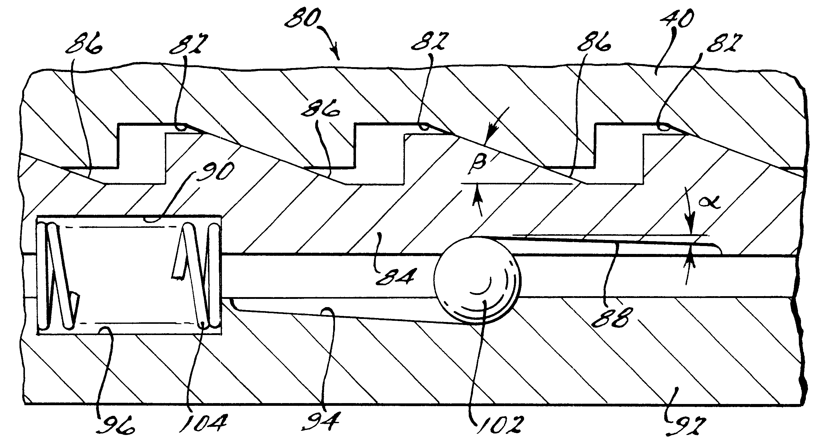
Referring to the drawings, a double stage ramp mechanism 80 for use in an electro mechanical engagement system for a friction clutch is shown. The double stage ramp mechanism 80 can be used in either a front axle or rear axle of an automotive vehicle. It may be used in any type of drivetrain system such as an all wheel drive, a front wheel drive, or a rear wheel drive.

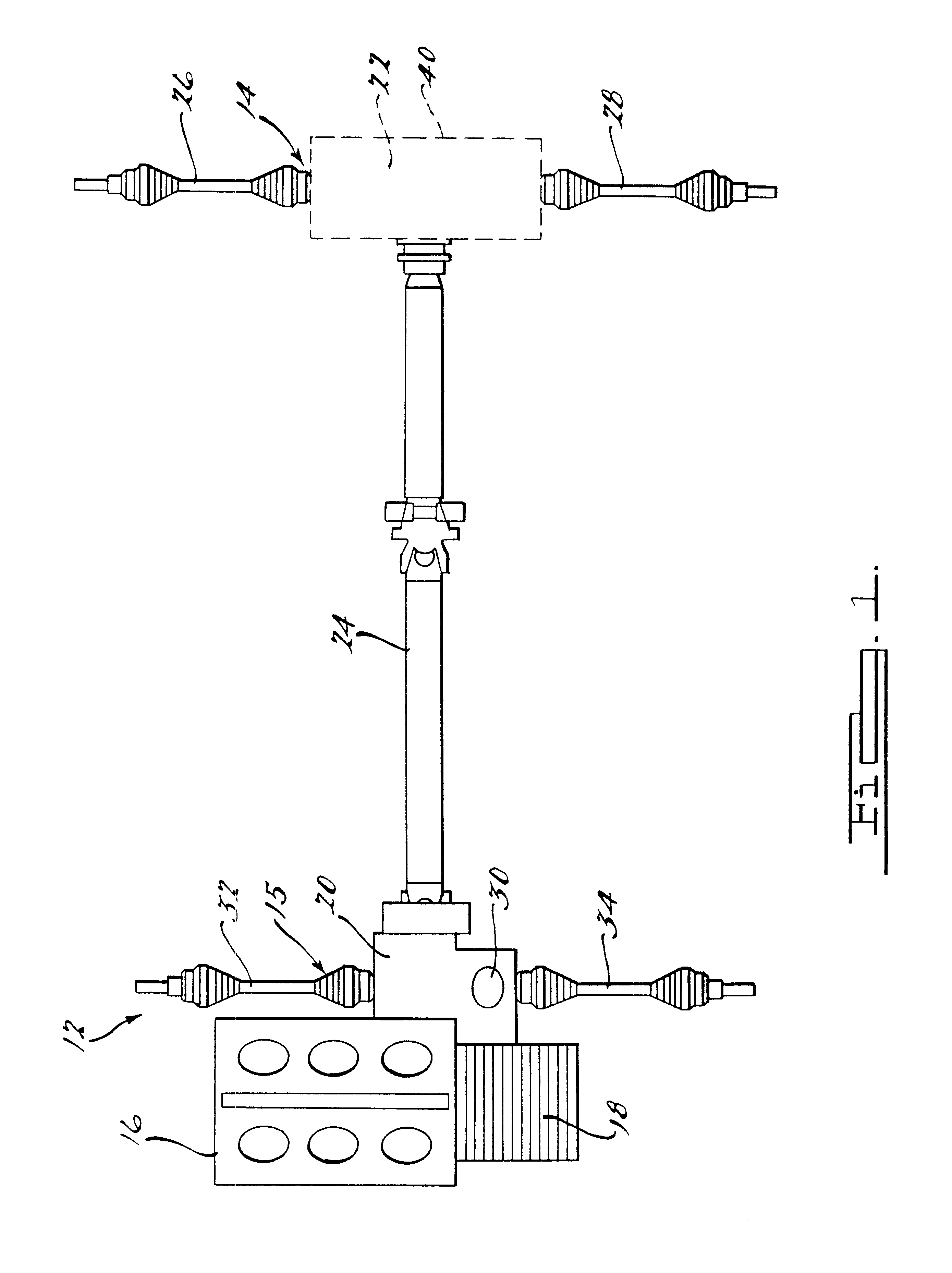
FIG. 1 schematically illustrates an all wheel drive or four wheel drive motor vehicle 12 that is primarily front wheel driven, however the present invention can also be used on a primary rear wheel driven vehicle. A motor vehicle 12 as shown in FIG. 1 is permanently driven by a front axle 15. The motor vehicle 12 is driven by power transferred from the engine 16 through a transaxle or gear box 18 which may be either an automatic or manual gear box. The power from the gear box 18 enters the power take off 20 of the drivetrain assembly and finally on through to the front differential 30. When there is a demand for power...


PUM


Abstract

An engagement mechanism for use in a vehicle includes a housing. The engagement mechanism also includes a first ball ramp disc engaging the housing on one side. The first ball ramp disc includes a first ramp on the side engaging the housing. The first ball ramp disc also includes a second ramp having a predetermined angle on the side opposite of the side engaging the housing. The engagement mechanism further includes a ball ramp disc adjacent to the first ball ramp disc on a side opposite of the side engaging the housing which is rotatably driven. The engagement mechanism also includes a spring element arranged between the first ball ramp disc and the second ball ramp disc. The engagement mechanism is used to engage a friction clutch pack of a vehicle drivetrain system.

Description

1. Field of the InventionThe present invention relates generally to engagement systems for use in an automotive vehicle, and more particularly relates to an electro mechanical engagement system for use in combination with a friction clutch to control the torque in the driveline of a vehicle.2. Description of Related ArtTorque distribution systems in automotive vehicles have been known for many years. The torque distribution systems are used on either a front axle or a rear axle or between the axles of an automotive vehicle. Generally, the torque distribution systems deliver torque to a wheel at all times at a fixed percentage or in an on demand manner. Torque distribution systems have some type of engagement system that will engage a friction clutch which includes a plurality of plates therein. Many types such as electrical, hydraulic and mechanical or electro mechanical systems have been designed for engaging the friction clutch. One of the more popular existing designs is the use ...

Claims


Application Information

Patent Timeline
Patent Type & Authority Patents(United States)
IPC IPC(8): F16H48/00F16H48/30F16D27/00F16D23/12F16H48/20F16H48/22F16H48/295F16H48/34
CPCF16D28/00F16H48/22F16H48/30F16H48/34F16H48/295F16D27/004F16H2048/343F16H2048/204
Inventor GASSMANN, THEODOR
Owner GKN DRIVELINE NORTH AMERICA
Why Eureka
Try Eureka