Method of cooling an optical fiber while it is being drawn

a cooling method and optical fiber technology, applied in the field of cooling an optical fiber while it is being, can solve the problems of eccentricity of the fiber in the coating and with the quality of the coating, and technical problems can arise, so as to reduce the attenuation of the fiber, improve the cooling effect of the optical fiber, and reduce the scattering of rayleigh back

Inactive Publication Date: 2003-06-10
DRAKA COMTEQ BV
View PDF9 Cites 25 Cited by
  • Summary
  • Abstract
  • Description
  • Claims
  • Application Information

AI Technical Summary

Benefits of technology

An object of the present invention is to alleviate the above drawbacks of prior art cooling systems by improving the cooling of an optical fiber during drawing. One particular object of the invention is to reduce Rayleigh back scattering significantly, compared to prior art cooling systems, and therefore to reduce the attenuation of the fiber fabricated by drawing using the cooling method of the invention.
In other words, the above temperature, referred to as the critical temperature, is related to the glass transition temperature associated with Rayleigh back scattering in the core of the fiber. The glass transition temperature associated with Rayleigh back scattering is a thermodynamic parameter characteristic of the disorder of the glass, and more precisely of variations in density which contribute to Rayleigh back scattering. The state of disorder achieved during solidification of the glass of the core of the fiber is that found in the finished fiber after drawing and the aim is to reduce the variations in density. The method of the invention advantageously provides better control over cooling of the optical fiber, which minimizes variations in the density of the glass.
One advantage of the method of the invention is that it complies with economic constraints, which limit the height of the tower available for cooling and require high drawing speeds. The presence of a fast cooling area eliminates the problem of the height of the drawing tower and / or the drawing speed.
Another advantage of the method of the invention is that a fast cooling area between the drawing furnace and a slow cooling area significantly improves the attenuation of the fiber obtained by the method of the invention, other conditions being equal. It is important to apply the fast cooling over a range of temperatures higher than said critical temperature, because if quenching is effected at the critical temperature, or at a lower temperature, the effect on Rayleigh back scattering can be disastrous and the attenuation of the fiber finally obtained can be greatly increased.

Problems solved by technology

Cooling the fiber between leaving the drawing furnace and entering the coating device is one of the major problems to be solved in drawing fibers, especially if it is required to increase the drawing speed.
It is well-known that the attenuation of the fiber depends on the cooling conditions, and moreover, if the temperature of the fiber on entering the coating device is too high, this can lead to problems both with the eccentricity of the fiber in its coating and with the quality of said coating.
The same technical problem can arise in this case.
Similarly, the same technical problem can arise in the fabrication of optical fibers based on polymer materials, in which the preform generally has a diameter of a few tens of millimeters, for example 80 mm, and a maximum length of a few tens of centimeters, for example 50 cm, and the temperature on leaving the drawing furnace generally lies in the range 200.degree. C. to 250.degree. C.
However, this would entail increasing the height of the drawing towers currently used, which would be much too costly, especially in terms of the investment required.
One of the main problems encountered in subsequent use of optical fiber cooled in the above way is that the cooling imposed on the fiber during its fabrication, on leaving the drawing furnace and before passing through the coating furnace, significantly increases the level of Rayleigh back scattering associated with the fiber and therefore increases the major part of the attenuation of the optical fiber ready for use.
Such methods are not satisfactory, however, in that they do not achieve sufficient reduction of the attenuation compared to the theoretical minimum attenuation.

Method used


Image

  • Method of cooling an optical fiber while it is being drawn
  • Method of cooling an optical fiber while it is being drawn
  • Method of cooling an optical fiber while it is being drawn

Examples


example

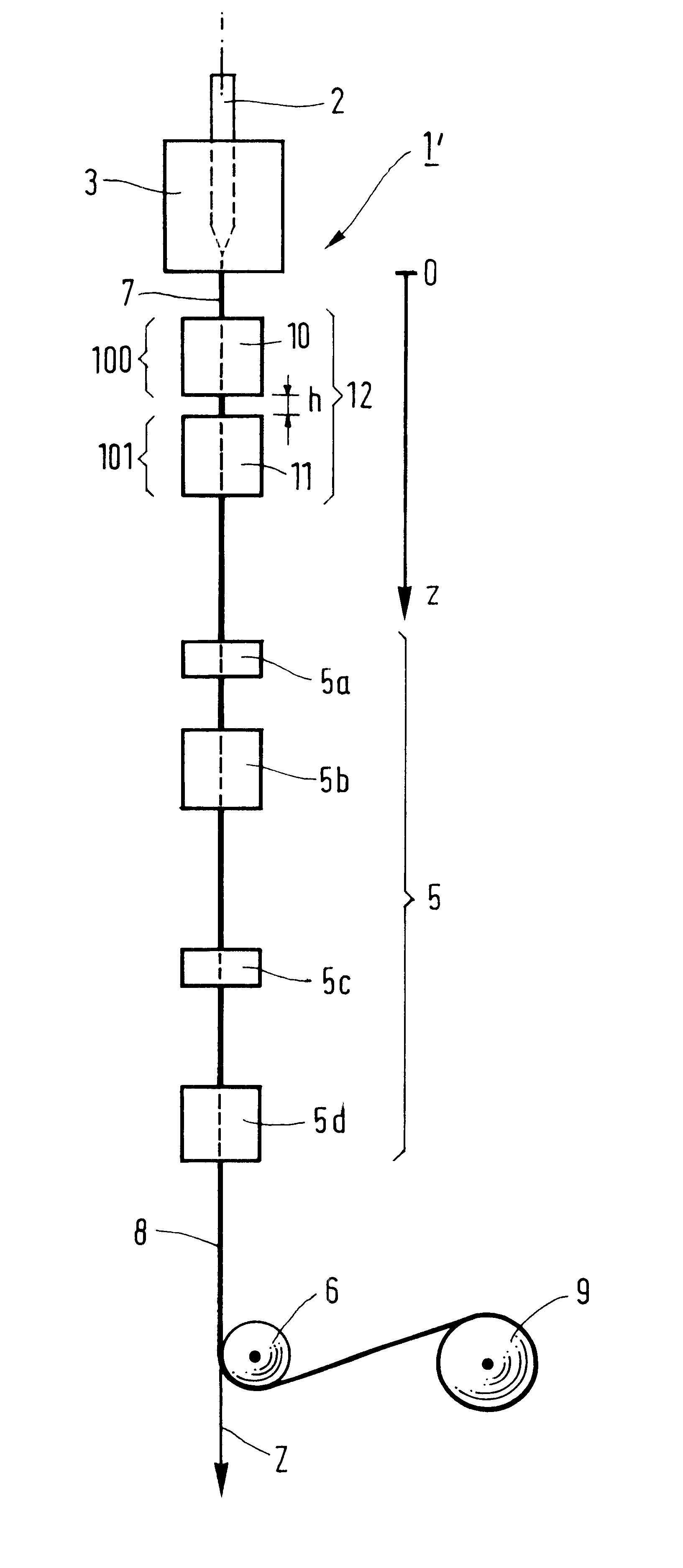
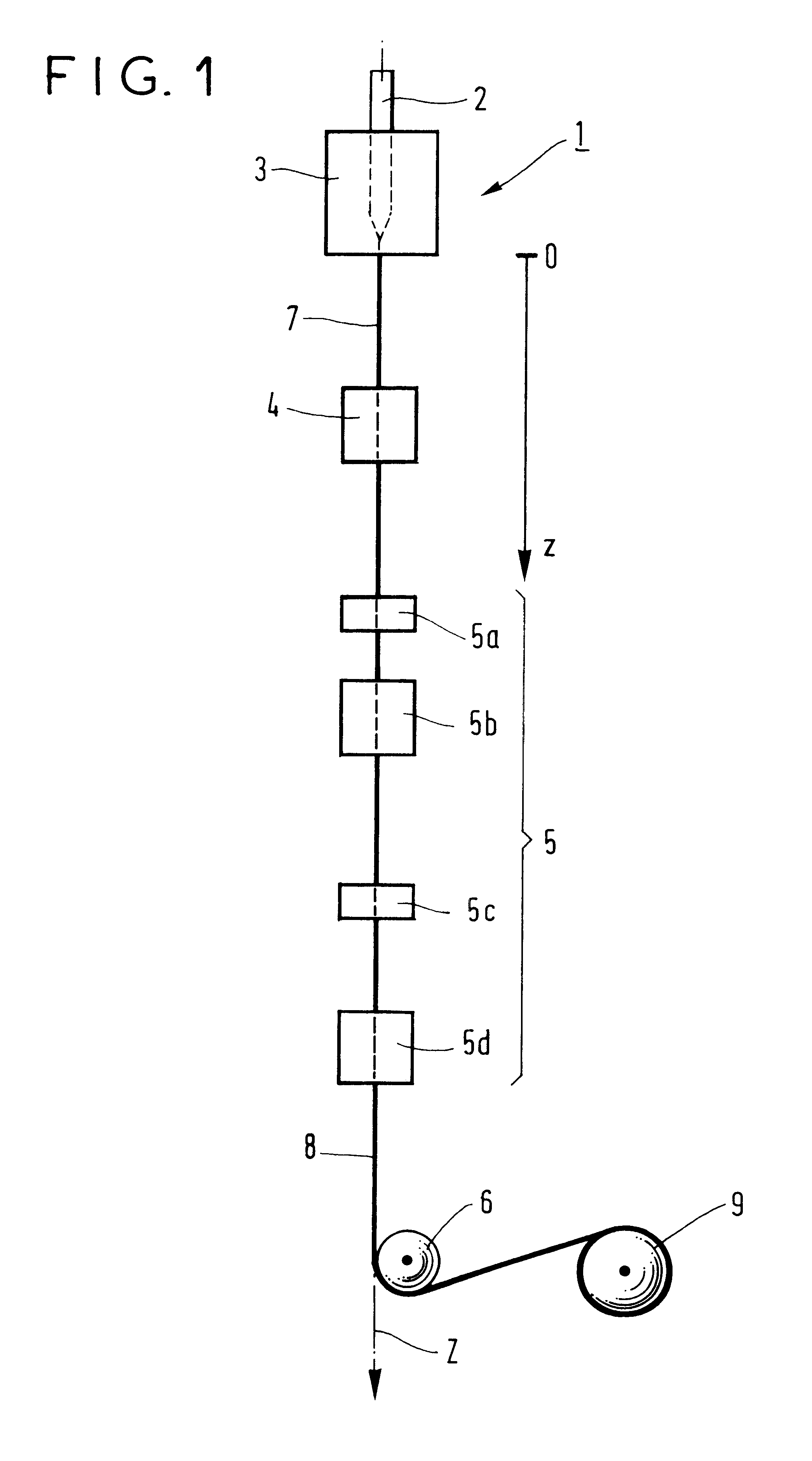
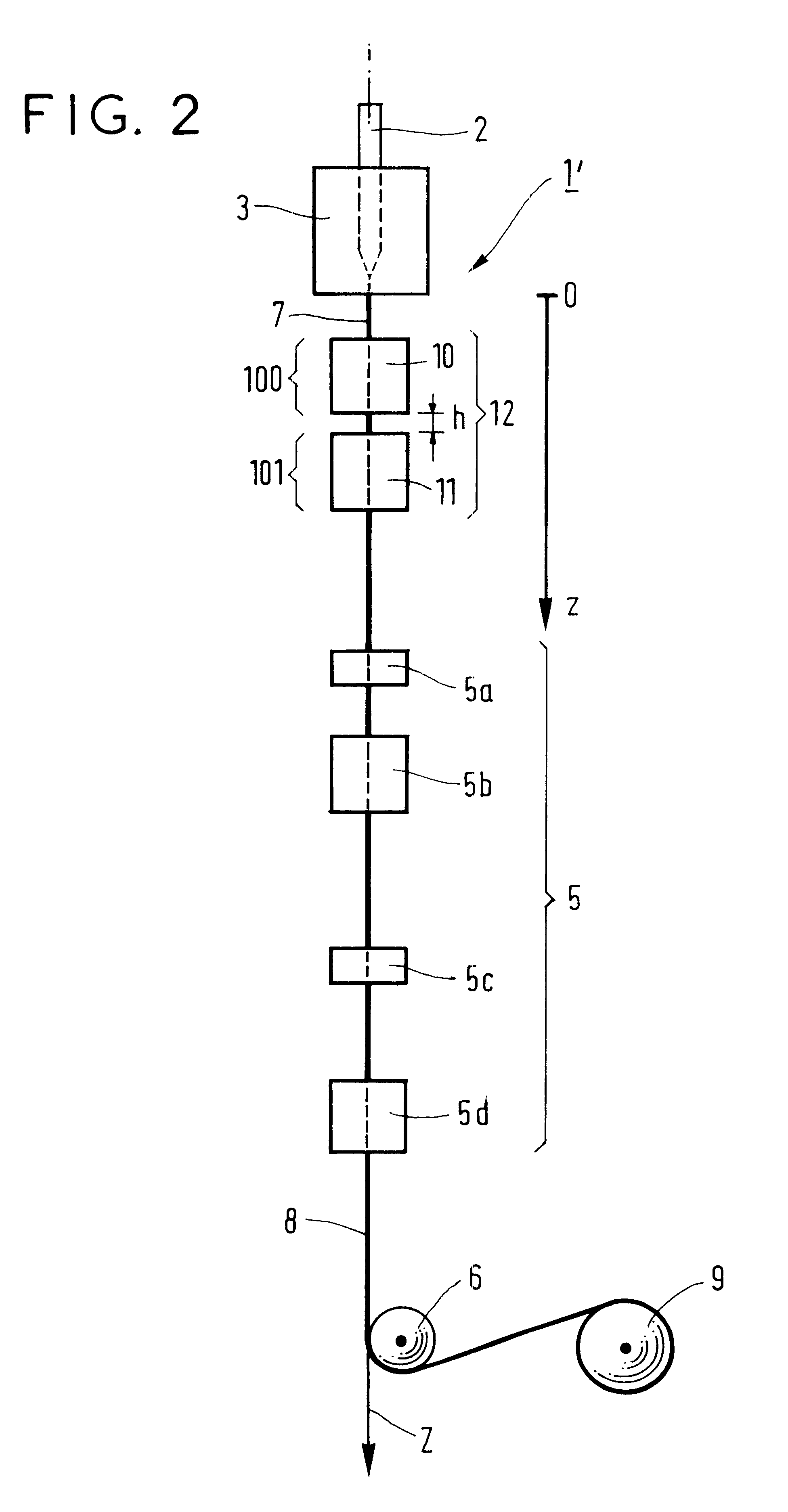
A cooling device 13 for implementing the invention like that shown in FIG. 3 was used on a drawing tower 1" which was of the type shown in FIG. 3 except that the tube 18 was omitted. The coated fiber made in said tower 1" was a standard silica-based fiber conforming to the G.652 standard.

The tube 14 was 25 cm long and its wall was maintained at a temperature of 15.degree. C. by heat exchange with a heat-exchange fluid, which was water in this example. The tube was 9 cm below the drawing furnace. The tube 14 defined a fast cooling area 102 in accordance with the invention, also referred to as the quenching area 102. A cooling fluid in the form of gaseous helium flowed inside the tube. The helium flowrate was adjustable to vary the temperature of the fiber on leaving said tube 14. In this example, said flowrate was fixed at 1 liter per minute (l / min) and the temperature of the fiber in the intermediate temperature area 105 was then 1500.degree. C.

The slow cooling device 19 had a total...


PUM

PropertyMeasurementUnit
temperatureaaaaaaaaaa
critical temperatureaaaaaaaaaa

Abstract

A method of cooling an optical fiber while it is being drawn through contact with at least one cooling fluid in at least one cooling area, wherein said method is such that fast cooling, i.e. cooling that is faster than cooling in the surrounding air, is followed by slow cooling, i.e. cooling slower than cooling in the surrounding air, the temperature of the fiber in an intermediate area between the two cooling areas lying in the range 1200° C. to 1700° C. in the case of silica glass fibers.

Description

The present invention relates to a method of cooling an optical fiber during drawing through contact with at least one cooling fluid in at least one cooling area.There are various categories of optical fiber: optical fibers based on oxide glass, optical fibers based on fluoride glass, and plastics material optical fibers based on polymer materials. Optical fiber based on oxide glass, usually silica glass, is manufactured by drawing a heated preform, which is a large cylinder of silica glass, optionally at least partly doped, whose diameter generally lies in the range 20 mm to 200 mm and whose length generally lies in the range 300 mm to 2000 mm. FIG. 1 is a diagrammatic view of a drawing tower 1. A preform 2 is melted in a drawing furnace 3 which heats the preform to a temperature of approximately 2000.degree. C. A fiber 7 obtained in this way is cooled initially by the surrounding air, then in at least one cooling device 4, and finally by the surrounding air again, before it is fed...

Claims


Application Information

Patent Timeline
Patent Type & Authority Patents(United States)
IPC IPC(8): B29D11/00C03B37/027C03B37/023C03B37/02G02B6/00
CPCB29D11/00721C03B37/0235C03B37/02718C03B2205/56C03B2205/55Y02P40/57
Inventor GUENOT, PHILIPPENICOLARDOT, MARCBOURHIS, JEAN-FRAN.CEDILLA.OISLAINET, ERIC
Owner DRAKA COMTEQ BV
Why Eureka
Try Eureka