Method of cooling an optical fiber while it is being drawn

a cooling method and optical fiber technology, applied in the field of cooling an optical fiber while it, can solve the problems of eccentricity of the fiber in the coating and with the quality of the coating, and technical problems can arise, so as to reduce the attenuation of the fiber, improve the cooling effect of the optical fiber, and reduce the scattering of rayleigh back

Inactive Publication Date: 2003-05-20
DRAKA COMTEQ BV
View PDF9 Cites 30 Cited by
  • Summary
  • Abstract
  • Description
  • Claims
  • Application Information

AI Technical Summary

Benefits of technology

An object of the present invention is to alleviate the above drawbacks of prior art cooling systems by improving the cooling of an optical fiber during drawing. One particular object of the invention is to conserve or even to reduce Rayleigh back scattering significantly, compared to prior art cooling systems, and therefore to conserve or even to reduce the attenuation of the fiber fabricated by a drawing process using the cooling method of the invention, and to preserve the mechanical strength of the fiber.
The method of the invention therefore has the advantage of enabling practical control over two important parameters of optical fiber made by a drawing process during which said cooling device is employed, namely its attenuation and mechanical strength. It has been found that the fast cooling profile in accordance with the invention has virtually no influence on the attenuation of said optical fiber.
Another advantage of the method of the invention is that it is consistent with economic constraints which limit the height of the part of the tower available for cooling and which lead to the use of high drawing speeds. The fast cooling area represents an improvement in terms of the height of the drawing tower and / or the drawing speed, and enables the length of the slow cooling area to be increased, in other words fiber attenuation to be improved. It also has the advantage that the temperature of the fiber on entering the slow cooling area can be controlled, regardless of the drawing speed.
In one implementation, the profile of the slow cooling is chosen so that the fictive temperature of the core is minimized and the profile of the fast cooling is then adjusted so that the fictive temperature of the cladding is maximized. It is therefore possible to provide means for implementing the given slow cooling profile on the drawing tower on which the fiber is drawn, in order to minimize the fictive temperature of the core, and then to provide means for implementing the fast cooling profile on said drawing tower to maximize the fictive temperature of the cladding. An alternative approach, and one that is usually preferred, is to give priority to controlling attenuation, and to be content with the resulting maximum mechanical strength.
Additional fast cooling advantageously reduces the temperature of the fiber to the entry temperature of the coating area without degrading the mechanical and optical properties of the fiber.

Problems solved by technology

Cooling the fiber between leaving the drawing furnace and entering the coating device is one of the major problems to be solved in drawing fibers, especially if it is required to increase the drawing speed.
It is known that the attenuation of the fiber depends on the cooling conditions, and moreover, if the temperature of the fiber on entering the coating device is too high, this can lead to problems both with the eccentricity of the fiber in its coating and with the quality of said coating.
The same technical problem can arise in this case.
Similarly, the same technical problem can arise in the fabrication of optical fibers based on polymer materials, in which the preform is generally smaller, generally having a diameter of a few tens of millimeters, for example 80 mm, and a maximum length of a few tens of centimeters, for example 50 cm, and the temperature on leaving the drawing furnace generally lies in the range 200.degree. C. to 250.degree. C.
However, this would entail increasing the height of the drawing towers currently used, which would be much too costly, especially in terms of the investment required.
One of the main problems encountered in subsequent use of optical fiber cooled in the above way is that the cooling imposed on the fiber during its fabrication, on leaving the drawing furnace and before passing through the coating device, significantly increases the level of Rayleigh back scattering associated with the fiber and therefore increases the major part of the attenuation of the optical fiber ready for use.
Such methods are not satisfactory, however, in that they do not achieve sufficient reduction of the attenuation compared to the theoretical minimum attenuation, without degrading the mechanical strength of the fiber.

Method used


Image

  • Method of cooling an optical fiber while it is being drawn
  • Method of cooling an optical fiber while it is being drawn
  • Method of cooling an optical fiber while it is being drawn

Examples


example

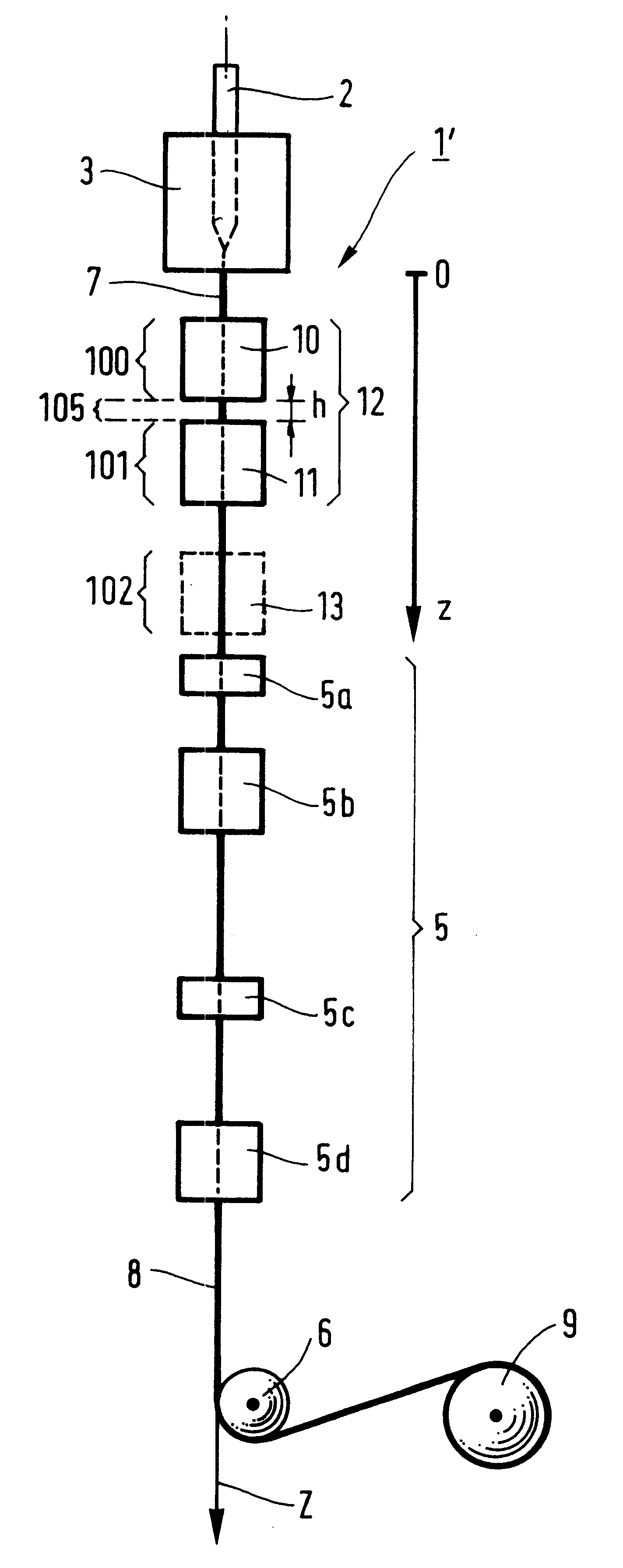
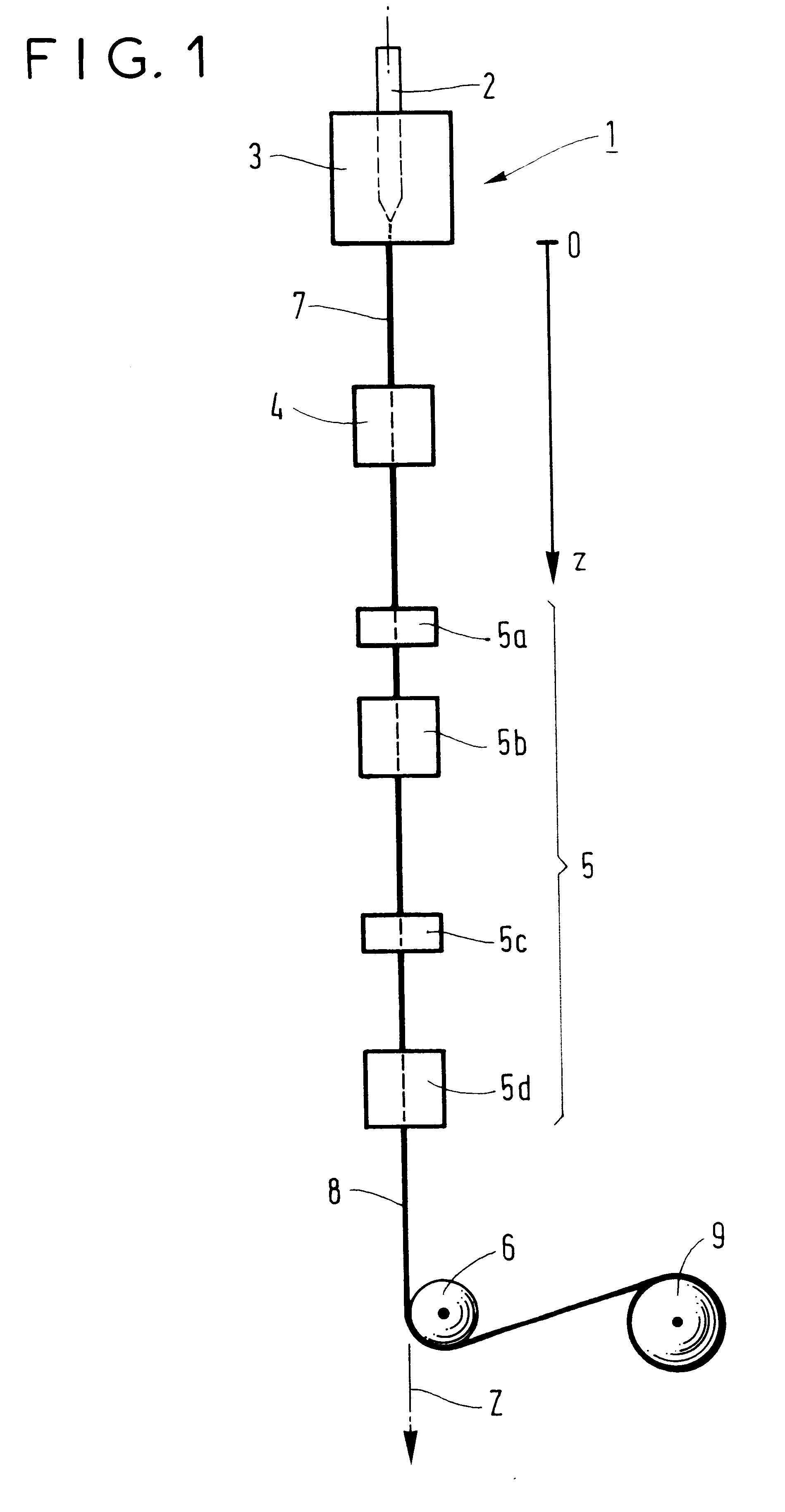
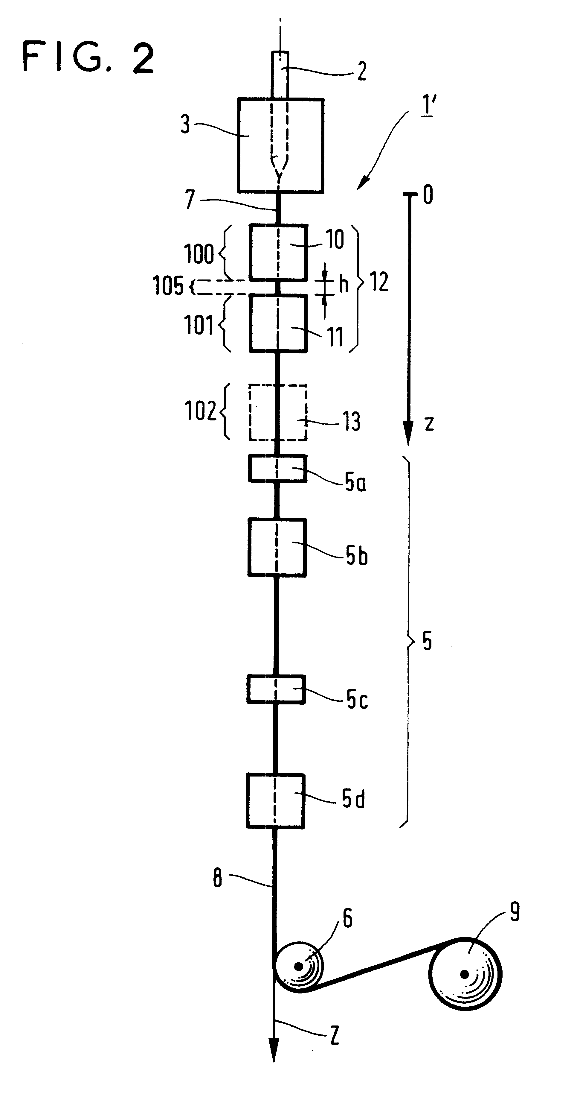
FIG. 3 shows a few cooling curves for the optical fiber in a prior art drawing device which, compared to the device shown in FIG. 2, does not include the devices 10 and 13. The temperature at the outlet from the drawing furnace 3 is 1800.degree. C., the total height between the drawing furnace 3 and the coating device 5 is 9 meters (m), and the drawing speed is 900 m / min. In the prior art arrangement shown there is only one slow cooling device 11 at the outlet from the drawing furnace 3. A heating device 11 which is 5 m long and has a given efficiency is provided. The distance z in meters from the bottom of the drawing furnace 3 (see FIG. 2) is plotted on the abscissa axis and the temperature T of the fiber in .degree. C. is plotted on the ordinate axis. The equation for the continuous parts of the cooling curves is of the following type:

T(.degree. C.)-T.sub.0 =(T.sub.e -T.sub.0).exp(-.alpha.*z),

where z is the distance in meters and .alpha., T.sub.e and T.sub.0 are glass relaxation ...


PUM

PropertyMeasurementUnit
temperatureaaaaaaaaaa

Abstract

A method of cooling an optical fiber during drawing through contact with at least one cooling fluid in at least one cooling area, wherein fast cooling, i.e. cooling that is faster than cooling in the surrounding air, from an initial temperature of the fiber to a temperature at the end of fast cooling of said fiber, is followed by slow cooling, i.e. cooling slower than cooling in the surrounding air, from a temperature of said fiber at the start of slow cooling to a temperature of said fiber at the end of slow cooling.

Description

The present invention relates to a method of cooling an optical fiber during drawing through contact with at least one cooling fluid in at least one cooling area.There are various categories of optical fiber: optical fibers based on oxide glass, optical fibers based on fluoride glass, and plastics material optical fibers based on polymer materials. Optical fiber based on oxide glass, generally silica glass, is manufactured by drawing a heated preform, which is a large cylinder of silica glass, optionally at least partly doped, whose diameter generally lies in the range 20 mm to 200 mm and whose length generally lies in the range 300 mm to 2000 mm. FIG. 1 is a diagrammatic view of a drawing tower 1. A preform 2 is melted in a drawing furnace 3 which heats the preform to a temperature of approximately 2000.degree. C. A fiber 7 obtained in this way is cooled initially by the surrounding air, then in at least one cooling device 4, and finally by the surrounding air again, before it is f...

Claims


Application Information

Patent Timeline
Patent Type & Authority Patents(United States)
IPC IPC(8): C03B37/027C03B37/023C03B37/02
CPCC03B37/0235C03B37/02718C03B2205/56C03B2205/55Y02P40/57
Inventor DUBOIS, SOPHIEORCEL, GERARDBOURHIS, JEAN-FRAN.CEDILLA.OIS
Owner DRAKA COMTEQ BV
Why Eureka
Try Eureka