
Arc suppression circuit

a technology of arc suppression circuit and arc suppression, which is applied in the direction of emergency protective arrangements for limiting excess voltage/current, ion beam tubes, transmission, etc., can solve the problems of electrical arcing mass, film coating defects, etc., and achieve the effect of suppressing electrical arcing and preventing shorting out of the power sour

Inactive Publication Date: 2003-06-10
LOS ALAMOS NATIONAL SECURITY
View PDF15 Cites 37 Cited by
  • Summary
  • Abstract
  • Description
  • Claims
  • Application Information

AI Technical Summary

Problems solved by technology

This positive feedback can cause massive electrical arcing to occur.
The electrical arcing can cause material to be vaporized, resulting in evaporation of impurities as well as ejection and deposition of physical material onto the substrate, creating defects in film being coated.

Method used


Image

  • Arc suppression circuit
  • Arc suppression circuit
  • Arc suppression circuit

Examples


Embodiment Construction

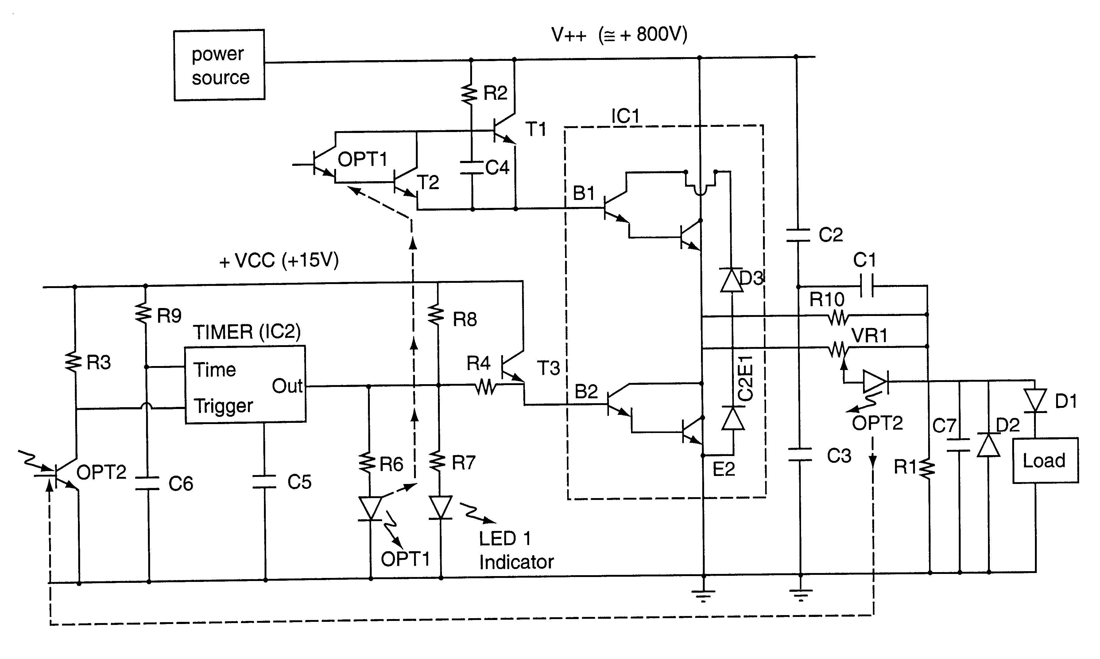
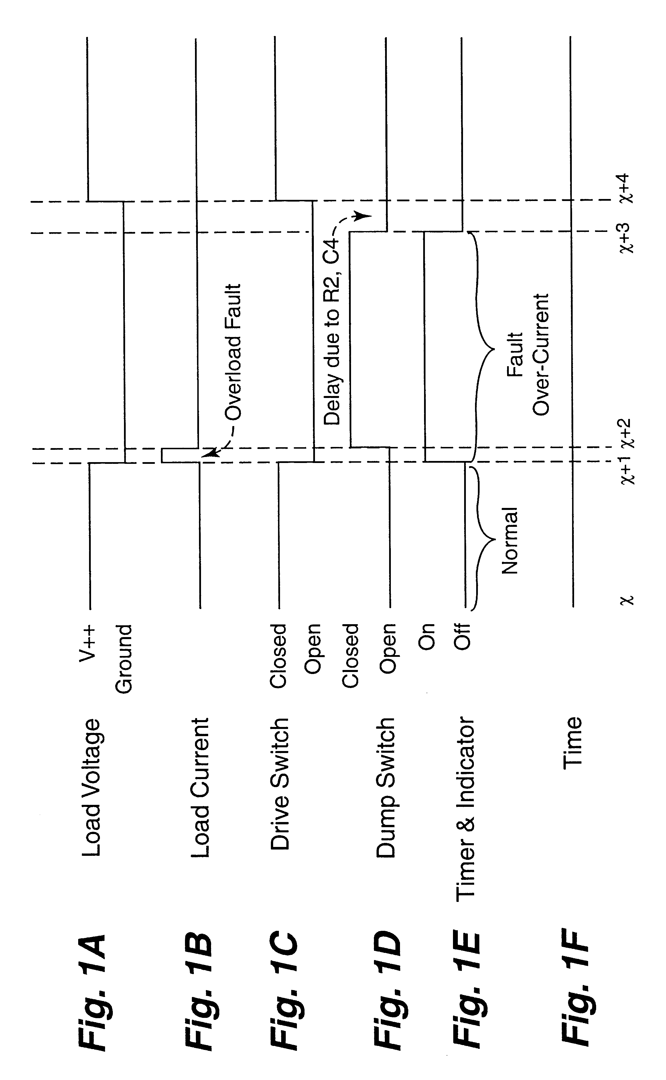
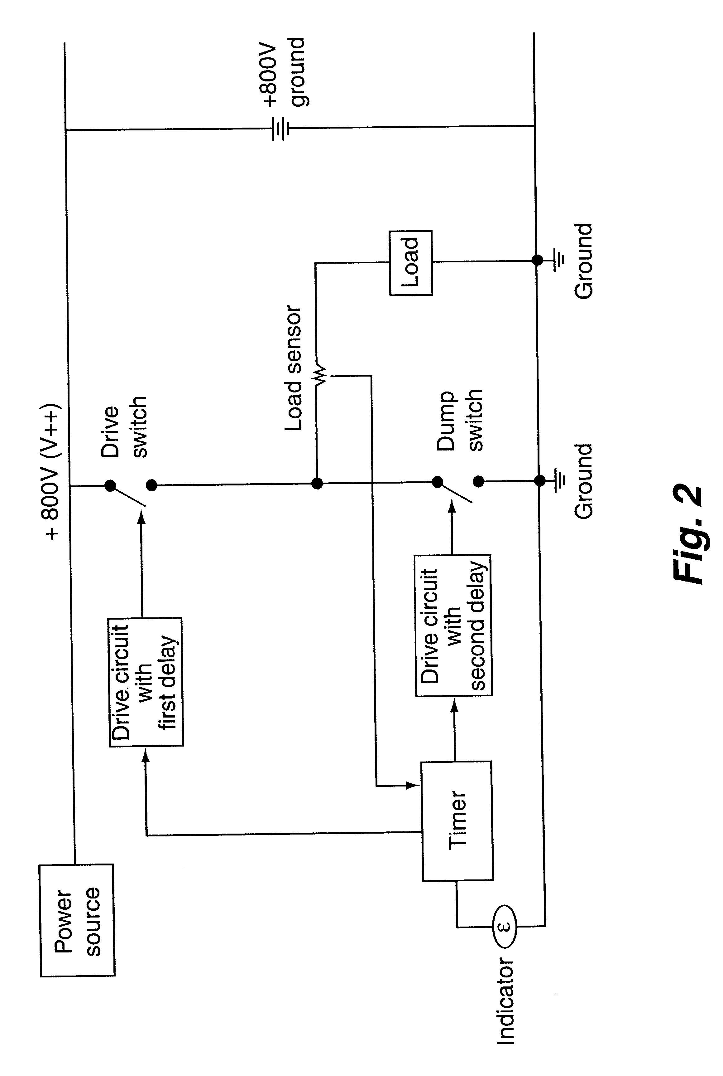
It has been discovered that an electrical circuit essentially operating as two switches with a timing device can be incorporated into the source voltage path of an ion beam source to suppress electrical arcing on the grid of the ion beam source. When an overload fault is detected by a load sensor or current shunt in the source voltage path current which activates and sustains the plasma on the grid, one switch (drive switch) opens the source voltage path to stop current flow to the grid. Then, after a delay from about one to about a hundred or more microseconds, a second switch (dump switch) closes to allow the excess charge and current to be drained from the ion beam source path to a ground rather than traveling through the plasma grid. Once the overload fault in the plasma is cleared, the dump switch is opened to disconnect the connection to ground. Then, after a delay from about one to about a hundred or more microseconds, the drive switch is once again closed to resume a flow of...


PUM


Abstract

A circuit for suppressing electrical arcing in an ion beam source or other plasma devices is provided. The arc suppression circuit of this invention detects current rises on ion beam source grids which cause arcing, disconnects the current flowing to the grid, and grounds the ion beam source to allow excess charge and current to be drained from the ion beam source rather than letting the charge and current arc on the grids of the ion beam source. A novel timing sequence is used for activating and deactivating the arc suppression circuitry to prevent shorting out of the power source. The arc suppressor circuits of this invention can be used on devices other than ion beam sources or plasma devices.

Description

This invention relates to circuitry for electrical arc suppression.This invention was made with government support under Contract No. W-7405-ENG-36 awarded by the U.S. Department of Energy. The government has certain rights in the invention.When an ion beam source is operating, small points of conductive material can develop on parts of the ion gun beam source and particularly on the plasma grid of the ion beam source. When this happens, the potential for increased current from those points can occur when the plasma is present. Enough current can flow through those sharp points or microdefects to release gas that can cause other areas on the ion beam source and the grids that are marginally arc stable to become arc sources themselves. This positive feedback can cause massive electrical arcing to occur. The electrical arcing can cause material to be vaporized, resulting in evaporation of impurities as well as ejection and deposition of physical material onto the substrate, creating d...

Claims


Application Information

Patent Timeline
Patent Type & Authority Patents(United States)
IPC IPC(8): H01J27/02
CPCH01J27/022
Inventor SPRINGER, ROBERT W.TOLMIE, DONALD E.
Owner LOS ALAMOS NATIONAL SECURITY
Learn More