Back light reflection sheet for liquid crystal

Inactive Publication Date: 2003-06-17
3M INNOVATIVE PROPERTIES CO
View PDF10 Cites 31 Cited by
  • Summary
  • Abstract
  • Description
  • Claims
  • Application Information

AI Technical Summary

Problems solved by technology

This type of reflection sheet, however, involves problems including that a high frequency current leaks from the fluorescent lamp, resulting in increased current consumption.
For this reflection sheet, however, the improvement in brightness over the brightness for the conventional reflection sheet is unsatisfactory, i.e., only 3 to 5%.
The 75 .mu.m-thick foamed polyester film which has been used up to now has a problem that, when the film is built in a back light device so as to surround the fluorescent lam

Method used


Image

  • Back light reflection sheet for liquid crystal
  • Back light reflection sheet for liquid crystal

Examples


examples 1 to 7

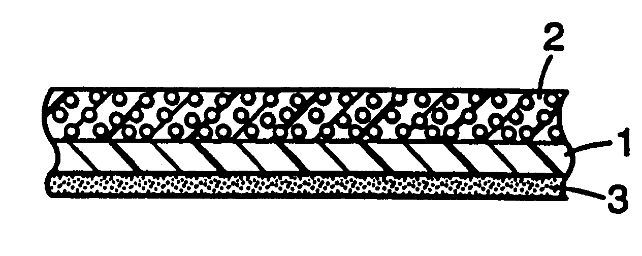
A white ink (a mixture of an acrylic / urethane binder with 50% by weight of Lamic.TM. F-22OHC White manufactured by Dainichiseika Color & Chemicals Manufacturing Co., Ltd. (titanium oxide)) was coated on one surface of a 36 .mu.m-thick white foamed polyester film (MELINEX.TM. 337, manufactured by ICI Co., Ltd.) (Examples 1 and 2 and 4 to 7) or a 36 .mu.m-thick unfoamed transparent polyester film (Example 3), which has been subjected to a treatment for facilitating bonding, to a thickness on a dry basis of 20 .mu.m, and the resultant coating was then dried, thereby preparing a white sheet. A reflective paint prepared according to a formulation specified in Table 3 was coated on the white ink layer of the white layer to a thickness on a dry basis of 50 .mu.m, and the resultant coating was then dried to prepare a reflection sheet. The reflection sheet thus obtained was slit into a strip having a width of 20 mm and a length of 219 mm. The strip was fixed with a pressure sensitive adhesiv...

examples 8 to 19

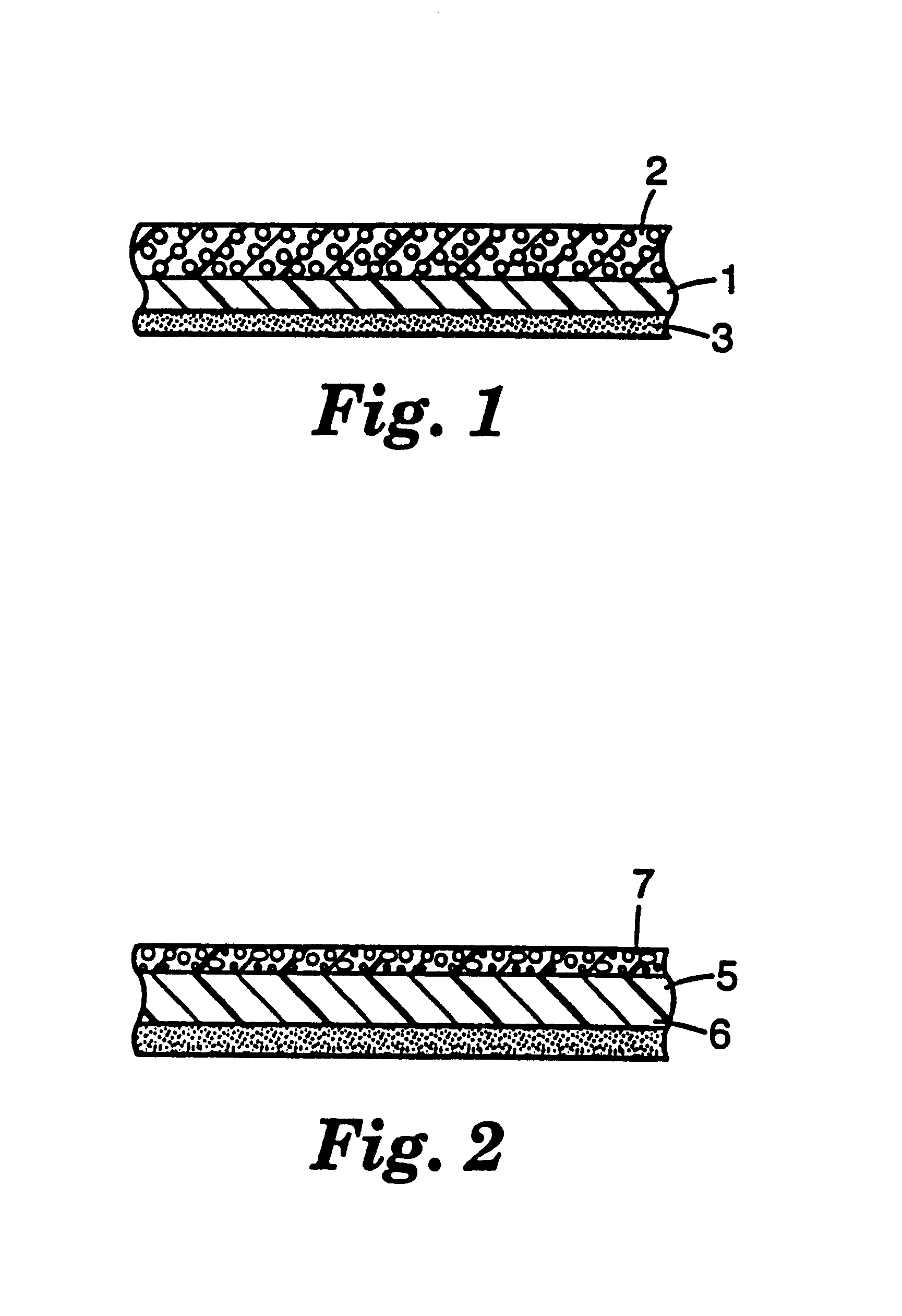
Each of reflective paints listed in Table 5 was coated on the surface of the same white sheet as used in Example 1 (Examples 8 and 10 to 19) or the same transparent sheet as used in Example 3 (Example 9) remote from the white ink layer to a thickness on a dry basis of 50 .mu.m, and the resultant coating was then dried, thereby preparing reflection sheets. For the reflection sheets thus obtained, the brightness was measured in the same manner as in Example 1. The relative brightness values are given in Table 5.

examples 20 to 22

Each of reflective paints (binder: a silicone-grafted type acrylic ester copolymer (trade name: Silicone-Acrylic Emulsion SX-8307 (A)04), Tg=5.degree. C., average light transmittance in the wavelength range of from 400 to 800 nm=100%) containing fillers listed in Table 5 was coated on the reflective coating layer of the reflection sheet prepared in Example 8 to a thickness on a dry basis of 5 .mu.m, and the resultant coating was then dried to form a layer (called a "top coat"), thereby preparing reflection sheets. For the reflection sheets thus obtained, the brightness was measured in the same manner as in Example 1. The relative brightness values are given in Table 5.


PUM

PropertyMeasurementUnit
Percent by massaaaaaaaaaa
Angleaaaaaaaaaa

Abstract

To provide a reflection sheet, using a thinner, lower stiffness film, for use in surrounding a straight tube type fluorescent lamp in an edge type liquid crystal display panel back light device, which reflection sheet can realize a higher brightness of the back light device. A reflection sheet comprising: a film support having a thickness of 25 to 50 mum and, applied on a surface of the support, a reflective paint coat comprised of a mixture of a resin binder of a (meth)acrylate copolymer with a small particle balloon having a particle diameter of 0.05 to 10 mum and an inside empty diameter to particle diameter ratio of 0.2 to 0.9.

Description

TECHNICAL FIELD OF INVENTIONThe present invention relates to a reflection sheet, particularly a reflection sheet disposed so as to surround a straight tube type fluorescent lamp provided along the edge of a light guide plate in an edge type back light device among back light devices of liquid crystal display panels, and a reflection sheet disposed on the reverse side of the light guide plate.PRIOR ARTIn an edge type back light device among back light devices of liquid crystal display panels, a straight tube type fluorescent lamp is disposed along the edge of a light guide plate. Part of light emitted from the fluorescent lamp on the light guide plate is directly guided to the light guide plate. The remainder of the light is reflected by a reflection sheet disposed so as to surround the fluorescent lamp and then enters the light guide plate. The light guided to the light guide plate is reflected by a light diffusing layer, which has been printed in a dot form on the reverse side of t...

Claims


Application Information

Patent Timeline
IPC IPC(8): G02B5/02
CPCG02B5/0242G02B5/0284Y10T428/256Y10T428/25Y10T428/31855
Inventor UCHIYA, TOMOAKISHIOTA, KOHOKADA, MITSUHIKONAGAMATSU, HIDEKINANBA, TAKAAKI
Owner 3M INNOVATIVE PROPERTIES CO
Why Eureka
Try Eureka