Method for forming pattern for transparent conductive layer

A technology of transparent conductive layer and transparent conductive film, applied in the direction of transparent dielectric, conductive layer on insulating carrier, circuit, etc., can solve problems such as difficult to remove accurately, difficulty, pattern short circuit, etc., and achieve excellent manufacturing efficiency and high manufacturing efficiency Effect

Inactive Publication Date: 2012-07-11
DIC CORPORATION
View PDF8 Cites 33 Cited by
  • Summary
  • Abstract
  • Description
  • Claims
  • Application Information

AI Technical Summary

Problems solved by technology

However, the conductive layer of silver nanowires before immobilization has weak adhesion to the substrate and is porous
Therefore, without damaging the bonding with the substrate, without damaging the conductive layer, and without damaging the network of silver nanowires, the nanowires are fixed by setting a patterned adhesive resin on it, or by uniformly It is very difficult to form a fixed pattern by exposing the coated adhesive resin to light
That is, there is a limit to the placement of the adhesive resin for accurate patterning on the conductive layer, and it is also difficult to accurately remove only the unfixed portion by washing or an adhesive roll.
In addition, even if the adhesive resin is uniformly provided on the conductive layer and a fixed pattern is formed by light irradiation, since the adhesiveness remains in the part not irradiated with light, it is difficult to accurately remove the part without leaving and form a fine pattern.
As a result, when removing the unfixed part or the uncured region of the produced transparent conductive layer, especially when these patterns are fine, and the line width or line pitch is narrow, the removal of the so-called narrow space part and the remaining of the thin line part are difficult. Difficult, there is a problem that the pattern short circuit caused by incomplete removal of the conductive layer and the disconnection caused by excessive removal are easy to occur on the fabricated conductive layer pattern

Method used


Image

  • Method for forming pattern for transparent conductive layer
  • Method for forming pattern for transparent conductive layer
  • Method for forming pattern for transparent conductive layer

Examples


Embodiment

[0123] Hereinafter, the present invention will be described more specifically by citing examples in the production of a transparent conductive layer film for a touch panel when the transparent conductive substance is a nanowire, but the present invention is not limited to these examples.

[0124](a) (Synthesis of silver nanowires)

[0125] Silver nanowires are described in Y.Sun, B.Gates, B.Mayers, and Y.Xia, "Crystalline silver nanowires by soft solution processing", Nano letters, (2002), 2(2) 165-168 Nanowires synthesized by dissolving silver sulfate in ethylene glycol and reducing it in the presence of polyvinylpyrrolidone (PVP) as a mold followed by the method of using polyalcohol as a reducing agent. That is, in the present invention, nanowires synthesized by a modified polyol method as described in Cambrios Technologies Corporation US Provisional Application No. 60 / 815627 are used.

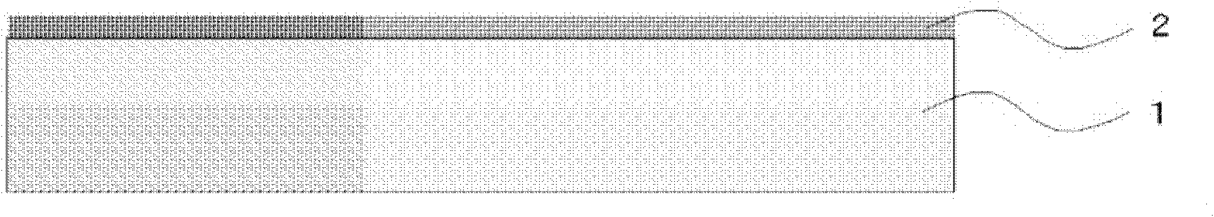
[0126] (b) (Formation of transparent conductive layer)

[0127] As metal nanowires to ...


PUM

PropertyMeasurementUnit
particle diameteraaaaaaaaaa
particle sizeaaaaaaaaaa
lengthaaaaaaaaaa

Abstract

Provided is a low cost method for easily forming a pattern on a transparent conductive layer that has a low electrical resistance, a high transparency, and is highly invisible to the eye. The method for forming a pattern on a transparent conductive layer comprises the following steps: a step (1) for releasably forming a transparent conductive layer on a substrate; a step (2) for forming a negative-patterned heat-sensitive adhesive layer on a support body; a step (3) for attaching the substrate and the support body in such a manner that the transparent conductive layer and the heat-sensitive adhesive layer adhere to each other; a step (4) for forming a pattern for the transparent conductive layer on the substrate by removing the support body from the substrate and by transferring the portions of the transparent conductive layer that adhered to the heat-sensitive adhesive layer onto the heat-sensitive adhesive layer; and a step (5) for fixing the transparent conductive layer on the substrate by applying a coating for forming a protective layer on the entire substrate formed with the aforementioned pattern for the transparent conductive layer and thereby impregnating the transparent conductive layer with said coating.

Description

technical field [0001] The invention relates to a method for forming a pattern of a transparent conductive layer on a substrate. [0002] In more detail, the present invention relates to the use of a base formed of a fine conductive substance with a peelable transparent conductive layer and a layer formed with a negative patterned bonding region, more preferably a heat-sensitive adhesive layer. body, and use the partial peeling of the transparent conductive layer to form a transparent conductive layer pattern on the substrate. Background technique [0003] In electronic devices utilizing light-emitting and light-receiving functions, various materials for forming transparent conductive layers and various transparent conductive layer films formed with transparent conductive layers on transparent substrates are mostly used as important functional components. Materials that pattern a transparent conductive layer to arrange a large number of conductive regions on a transparent s...

Claims


Application Information

Patent Timeline
Patent Type & Authority Applications(China)
IPC IPC(8): H01B13/00G06F3/041
CPCG06F2203/04112G06F3/044G06F2203/04103G06F3/041H05K2201/0108H05K3/046H05K2201/10128G06F3/0443G06F3/0446G06F2203/04111H01B5/14Y10T428/24802
Inventor 山崎嘉一早川智宫本雅史
Owner DIC CORPORATION
Why Eureka
Try Eureka