Panoramic refracting conical optic

a conical optic and panoramic technology, applied in the field of optical devices, can solve the problems of limited forward-looking angular resolution along the z-axis of the lens based on the two-dimensional diametrical geometry of the pal 10, difficult to machine with acceptable tolerances, and the three-dimensional realization of the lens based on the two-dimensional diametrical geometry of the pal 10 is difficult to achieve,

Inactive Publication Date: 2003-06-17
NASA
View PDF5 Cites 10 Cited by
  • Summary
  • Abstract
  • Description
  • Claims
  • Application Information

AI Technical Summary

Problems solved by technology

Unfortunately, the three-dimensional realization of a lens based on the two-dimensional diametrical geometry of PAL 10 is difficult to machine with acceptable tolerances.
Thus, the PAL based on the two-dimensional geometry described above is limited to use in expensive systems that can tolerate its high-cost of precision manufacturing.
Further, the PAL's forward-looking angular resolution along the Z-axis is limited due to the presence of concave surface 10C.

Method used


Image

  • Panoramic refracting conical optic
  • Panoramic refracting conical optic
  • Panoramic refracting conical optic

Examples


Embodiment Construction

)

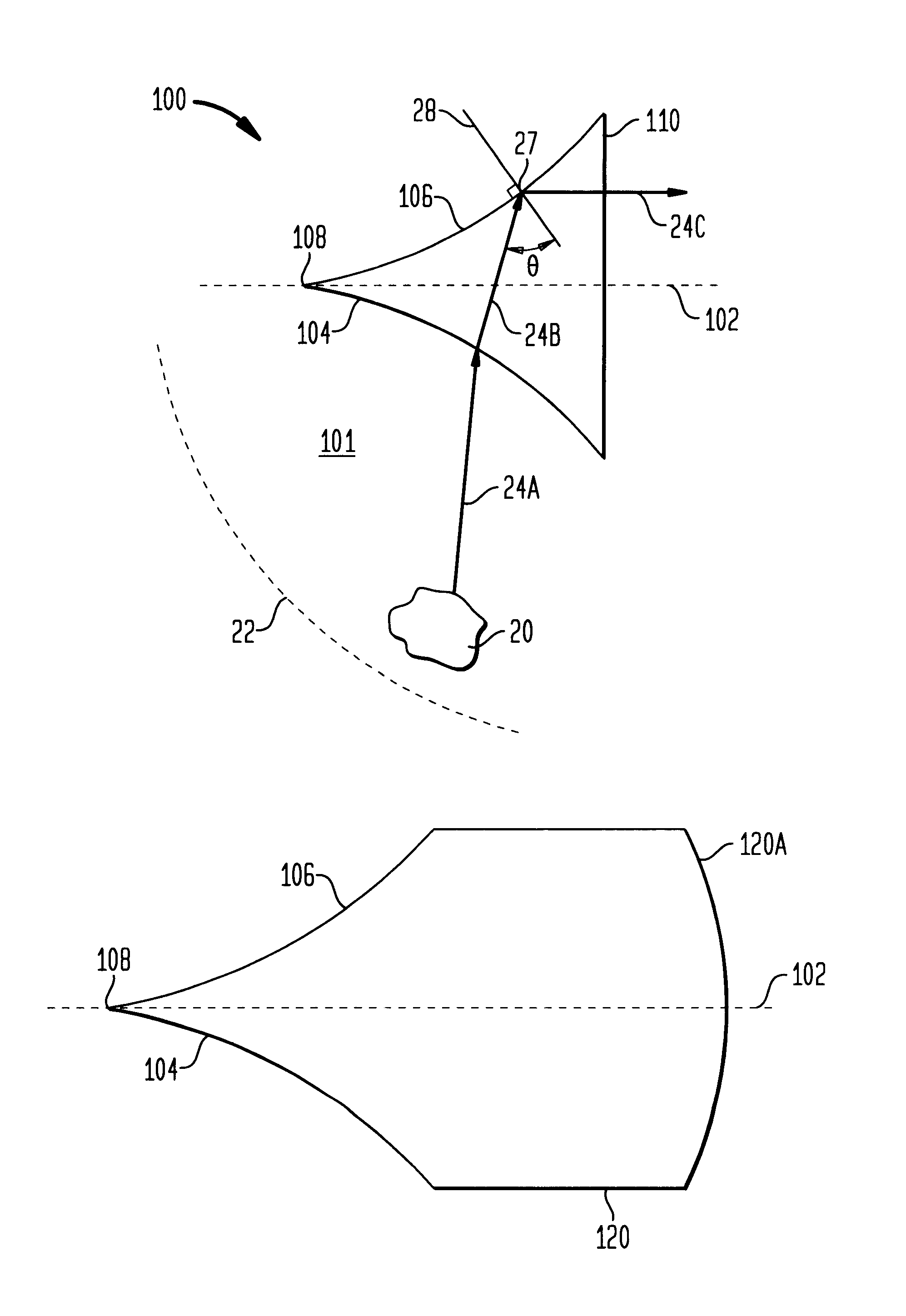
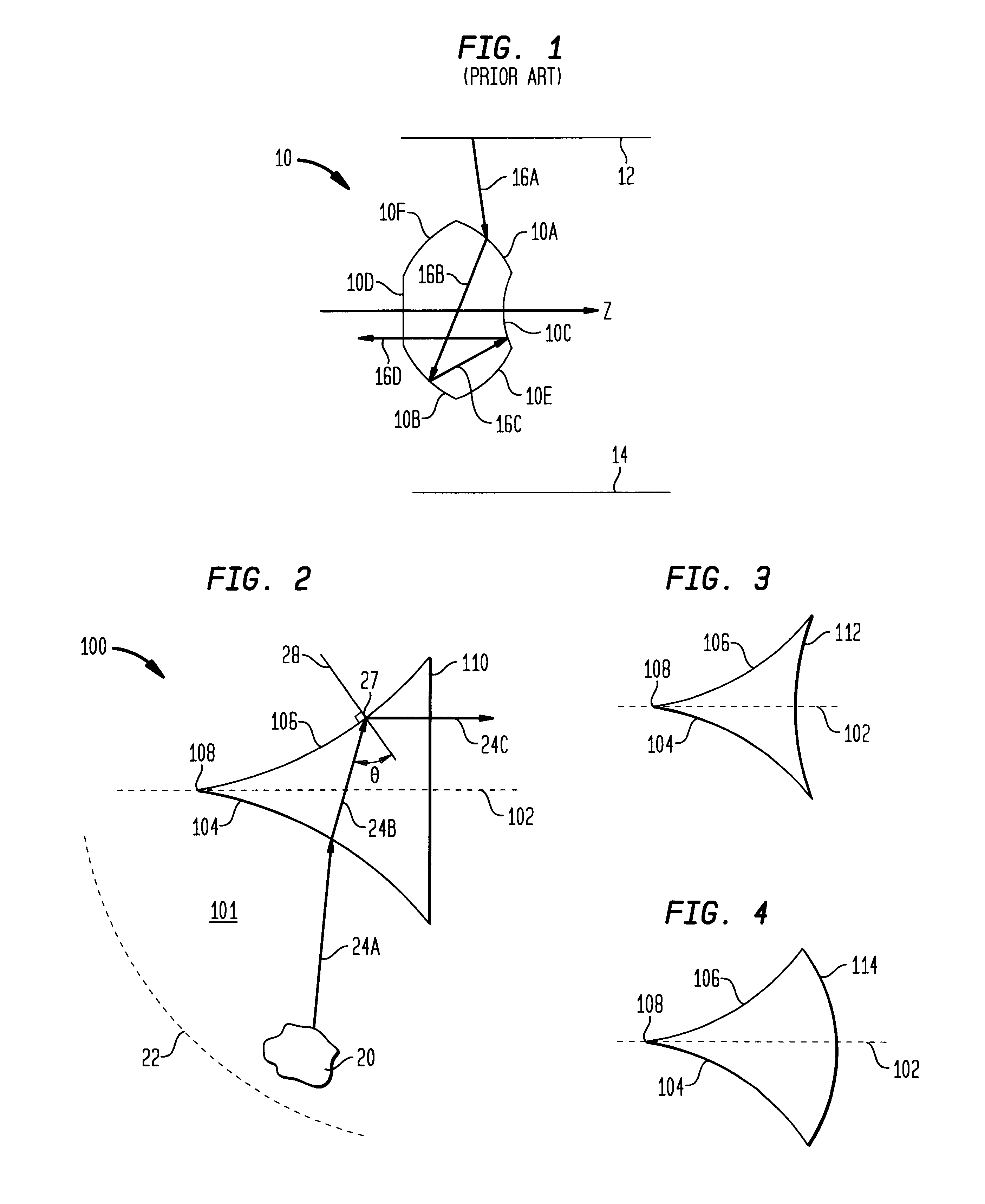
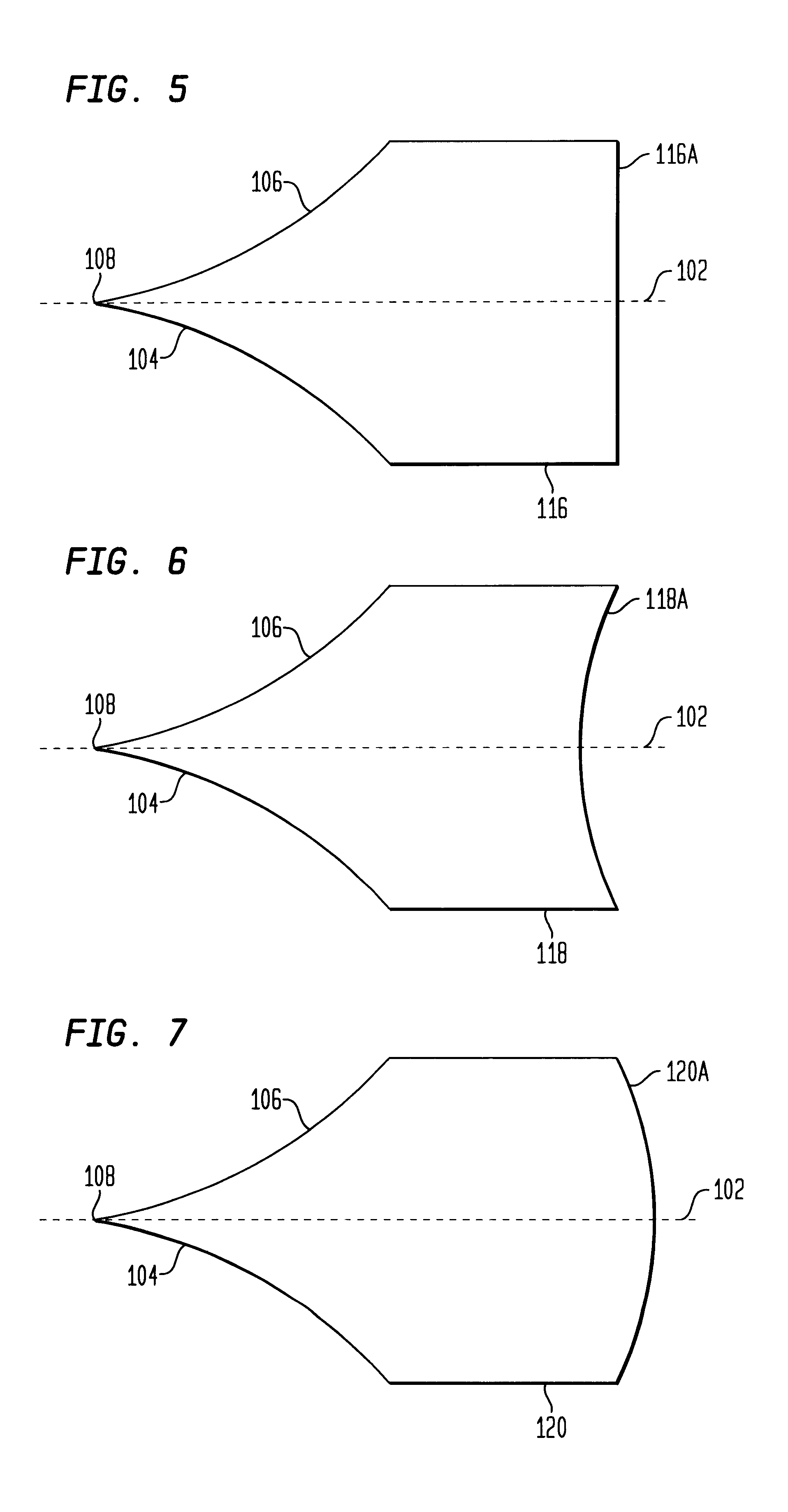
Referring again to the drawings, and more particularly to FIG. 2, a two-dimensional diametrical view of an embodiment of a panoramic refracting optic according to the present invention is shown and referenced generally by numeral 100. That is, the three-dimensional solid structure of the optic is achieved by rotating the view in FIG. 2 about the longitudinal axis 102 of optic 100. Accordingly, the present invention is a solid, conically-shaped, three-dimensional structure. Optic 100 is made from any optical material that permits the passage of light therethrough. Suitable materials include, but are not limited to, quartz glass, plexiglass, flint glass, boron glass, diamond, or any other optical material suitable for use in the manufacturing of lenses.

In the description to follow, optic 100 will be explained for its use in imaging objects lying in a semi-spherical or hemispherical scene about optic 100. However, it is to be understood that optic 100 could also be used to illuminate ...


PUM


Abstract

An optical device having a semi-spherical or hemispherical field-of-view is provided. A conically-shaped piece of optical material has an annular surface satisfying Snell's Law for total internal reflection with respect to light passing through the piece and incident on the annular surface from within the piece.

Description

ORIGIN OF THE INVENTIONThe invention was made by an employee of the United States Government and may be manufactured and used by or for the Government for governmental purposes without the payment of any royalties.1. Field of the InventionThis invention relates to optical devices. More specifically, the invention is an optical device capable of achieving a semi-spherical or hemispherical field-of-view.2. Description of the Related ArtImaging or illuminating cylindrical, semi-spherical or hemispherical scenes is generally accomplished using a plurality of angular field-of-view cameras / lenses positioned to characterize the necessary field-of-view. Typically, the angular field-of-view of each camera / lens is on the order of 120.degree. or less. Thus, multiple cameras / lenses are required to simultaneously view or illuminate, for example, the traffic flow at an intersection, the entire area surrounding a vehicle or structure, or the interior of a room or other structure.A solution to this...

Claims


Application Information

Patent Timeline
Patent Type & Authority Patents(United States)
IPC IPC(8): G02B13/06G02B17/08
CPCG02B13/06
Inventor LINDNER, JEFFREY L.
Owner NASA
Why Eureka
Try Eureka