Knee prosthesis

a knee and prosthesis technology, applied in the field of knee prosthesis, can solve the problems of inability to retain the posterior cruciate ligament, reducing the resistance of the knee,

Inactive Publication Date: 2003-06-24
CORIN
View PDF5 Cites 136 Cited by
  • Summary
  • Abstract
  • Description
  • Claims
  • Application Information

AI Technical Summary

Problems solved by technology

Finally, the height of the ramp of the tibial plateau requires considerable resection of the femoral epiphysis, which clearly leads to a considerable reduction of its resistance.
Total prostheses of the knee as described above have certain drawbacks: it is impossible to retain the posterior cruciate ligament because of the central placement of the convex cam between the two condyles.

Method used


Image

  • Knee prosthesis
  • Knee prosthesis
  • Knee prosthesis

Examples


Embodiment Construction

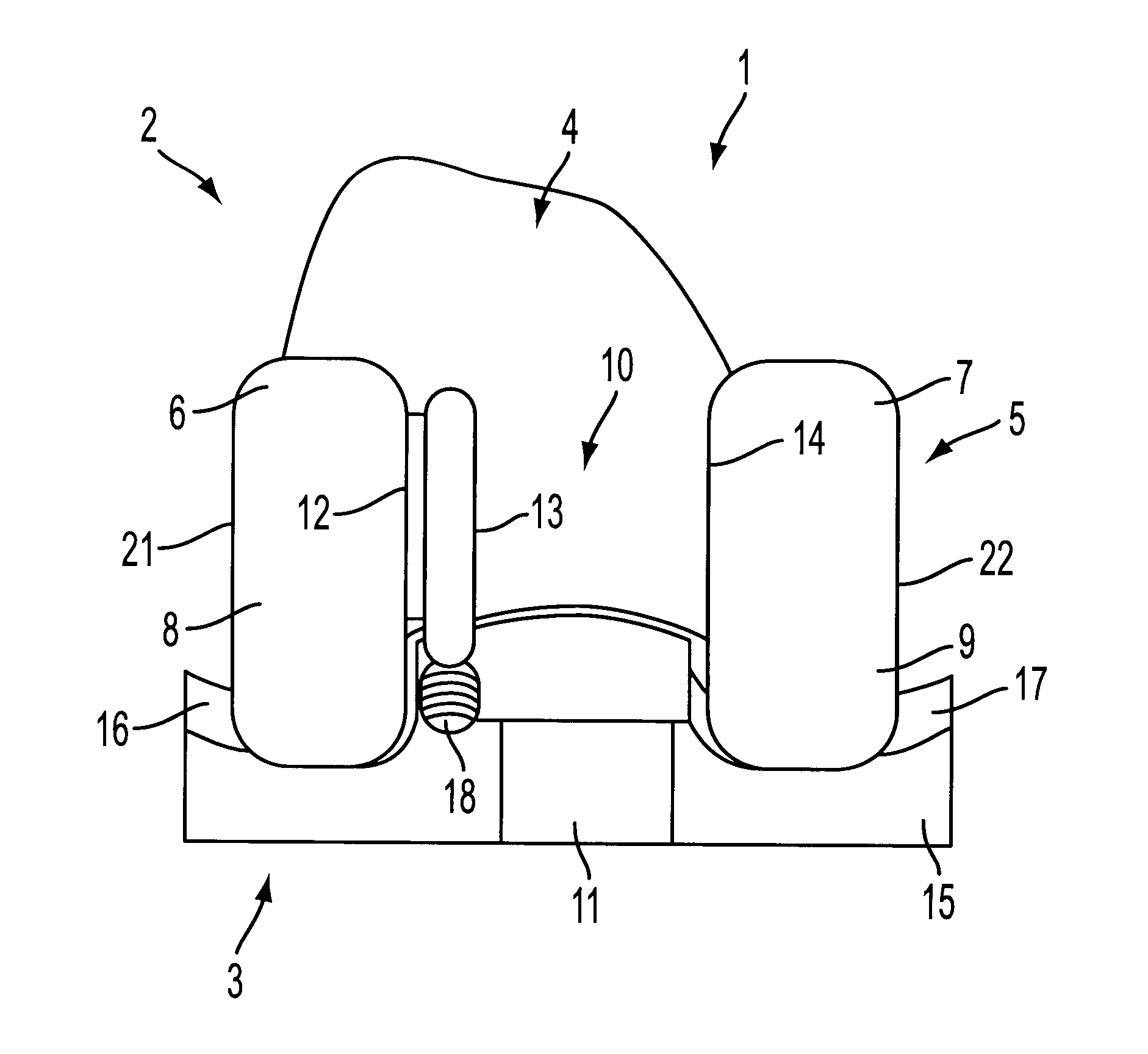
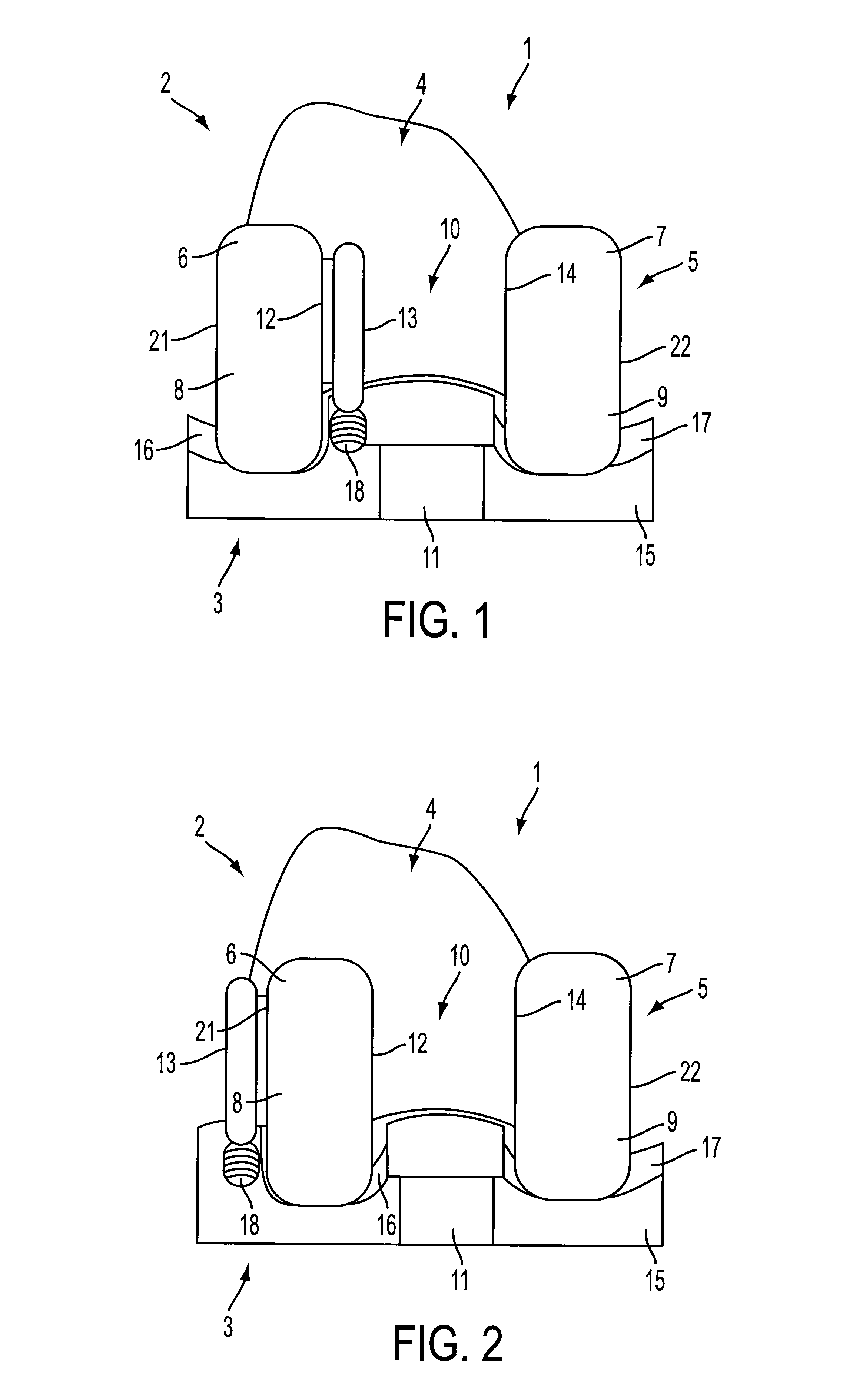
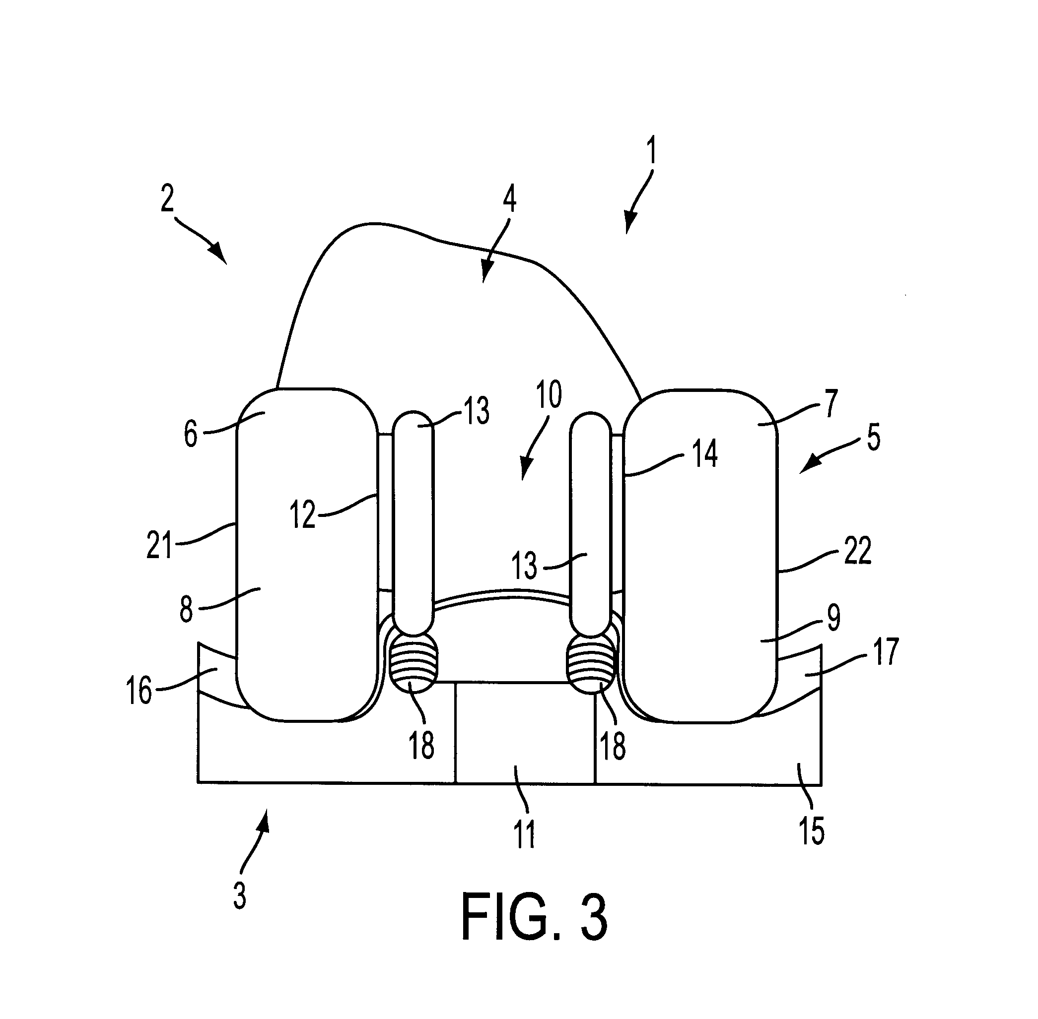
FIG. 1 displays a total prosthesis of the knee 1 which essentially comprises a femoral element 2 and a tibial plateau 3.

In transverse section, the femoral element 2 is U-shaped overall i.e. it is formed from an initial anterior wing 4 which extends by way of a second posterior wing 5.

The flat internal surfaces of both these wings are intended to come together with the flattened ends of the femoral epiphysis (not shown) produced by sectioning the epiphysis anteriorly and posteriorly.

The posterior wing 5 comprises of two distinct and parallel cambers 6 and 7 integral with the anterior camber 4. The external surface of cambers 6 and 7 and the anterior wing 4 have a curved shape defining the limits of two lateral condyles 8 and 9 which may be symmetrical or asymmetrical depending on the usage of the prosthesis 1.

The external condyle 8 is separated from the internal condyle 9 by a free space 10 which is in communication with a space or notch 11 made in the posterior part of the tibial pl...


PUM


Abstract

Total prosthesis of a knee including a femoral element fitted with two condyles, a first of the condyles being external, a second of the condyles being internal, and a tibial plateau fitted with custom-made recesses to hold the condyles, wherein at least one of the condyles is integral on one of its sides with a convex cam ensuring posterior stability of the prosthesis. The tibial plateau has at least one track placed in the immediate vicinity of the recess holding the condyle integral with the cam, the at least one track being circumscribed by at least one curved abutment and at least one horizontal recess between posterior and anterior extremities of the tibial plateau. Provision is made between the condyles of the femoral element and the recesses of the tibial plateau for a free space and a notch for passage of a posterior cruciate ligament of a knee.

Description

1. Field of the InventionThe present invention pertains to the field of improvements in total knee prostheses which comprise, as is customary, a femoral element and a tibial plateau. The femoral element is used to replace the destroyed condyles of the femur, while the tibial plateau replaces the defective upper part of the tibia.2. Discussion of Background InformationProstheses of this type are already available. They are essentially sliding prostheses, with or without preservation of the posterior cruciate ligament, and in which the femoral element moves over a small surface area in relation to the tibial plateau.Document GB-A-2 067 412 describes a knee prosthesis in which the femoral element is fitted between its two condyles with a passage which terminates in a convex cam. The tibial plateau of the present prosthesis has recesses to hold the condyles and a concave ramp rising up toward the femoral element and stretching widely between both its condyles.When the cam is engaged wit...

Claims


Application Information

Patent Timeline
Patent Type & Authority Patents(United States)
IPC IPC(8): A61F2/38
CPCA61F2/3886
Inventor TORNIER, ALAIN
Owner CORIN
Why Eureka
Try Eureka